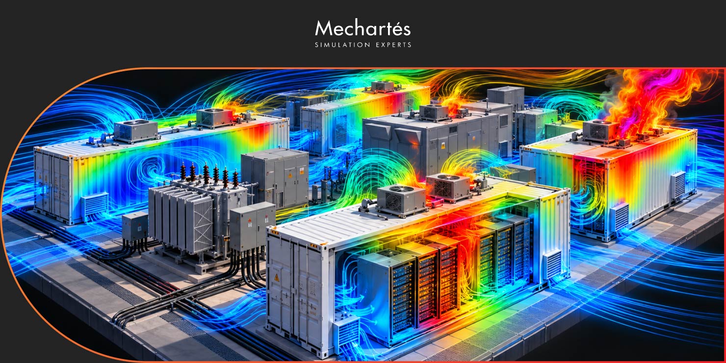
Battery Energy Storage Systems at utility scale have a lot going on thermally. Lithium-ion batteries, including LFP chemistry, need consistent temperature control to stay within safe operating limits. Put those systems outdoors alongside a solar PV plant in a high-ambient climate, and the thermal environment becomes more complex than a standard design review usually captures.
CFD analysis for BESS plants gives engineers a way to examine airflow and temperature distribution across a proposed layout before construction begins. At Mechartes, this is one of the more detailed simulation scopes we run, because the interactions between equipment, local climate conditions, container spacing, and the overall layout don’t always surface until you model them properly.
A typical site has BESS containers, PCS (Power Conversion System) units, HVAC cooling equipment, and electrical enclosures sitting close together. Each piece of equipment either generates heat or depends on cooled air to operate. The layout determines how that heat moves through the site.
HVAC intake temperatures are among the first things to check in any BESS CFD analysis. If hot exhaust air from adjacent containers or solar-heated ground recirculates back into cooling intakes, the cooling system has to work harder to maintain battery temperatures within their operating window. Dense container arrangements can also trap heat and create localized thermal buildup that isn’t visible from a plan view.
Wind direction and speed add another variable. A layout that performs well with prevailing winds from one direction can behave quite differently when the wind shifts. CFD modeling tests those variations systematically, covering the range of conditions the site will actually see across a year.
The analysis starts with a model of the full plant layout, covering container geometry, equipment spacing, ground conditions, and local climate parameters for the site. We then simulate ambient airflow behavior, temperature distribution across equipment clusters, heat accumulation zones, and the effectiveness of the ventilation arrangements.
Those outputs are compared directly with the equipment limits supplied by the project team. That comparison shows where intake temperature concerns exist, identifies areas where hot air is recirculating, and indicates whether the cooling system is likely to be running close to its limits under peak ambient conditions.
Wind direction sensitivity is a standard part of this scope. The site’s thermal behavior can shift considerably depending on whether the prevailing wind is channeling heat away from equipment clusters or trapping it between them.

CFD analysis for BESS facilities covers more than normal operating conditions. Thermal runaway in a lithium-ion battery can involve off-gassing, high-temperature gas release, rapid heat transfer to nearby containers, and smoke dispersal across adjacent equipment. Container separation distances and the placement of neighboring PCS units can significantly affect how a fire event develops.
Modeling a defined fire scenario can evaluate hot gas and smoke dispersion from a single container, temperature impact on adjacent BESS units, the thermal exposure of neighboring PCS equipment, and how those outcomes shift at different separation distances. These results give the project team something concrete to work from while layout decisions can still be changed.
One clarification worth stating plainly: the model works from defined event assumptions and selected boundary conditions. It examines the consequences of a specified scenario, but it doesn’t predict fire propagation, and it needs to be read alongside the site’s broader fire risk assessment.
Solar PV arrays, ground cover, and equipment spacing all influence local air temperatures across the plant. Ground temperature under direct solar exposure can run significantly higher than the ambient air temperature, and that elevation transfers into the air moving through equipment zones.
In dense layouts, those temperature effects compound. BESS CFD analysis at the plant level can identify high-temperature zones, flag areas of poor circulation, and show the additional thermal load on battery cooling systems in those locations. That information directly informs where to position HVAC intakes and whether additional row spacing is warranted.
CFD analysis for BESS is applicable across a range of project types, including utility-scale storage facilities, solar-plus-storage hybrid plants, HVAC performance validation, and electrical substation thermal review. It’s also used for sensitivity studies where the design team needs to understand how different ambient temperature assumptions or wind conditions affect cooling performance.
At Mechartes, this work is typically done during the design phase, when there’s still flexibility to change container spacing, reposition HVAC intakes, adjust the cooling layout, or revisit fire scenario assumptions before construction.
BESS CFD analysis reveals interactions between layout, climate, and equipment that won’t show up on a plan drawing. For sites where high ambient temperatures or tight equipment spacing don’t leave much margin, it gives the project team a basis for decisions grounded in what the model actually shows.
BESS thermal and fire safety analysis is an active part of our work at Mechartes, across utility-scale storage facilities and solar-plus-storage projects in the Middle East and beyond. If you’re working through a BESS layout and want to know what CFD analysis would cover for your site, get in touch.
BESS CFD analysis examines airflow, temperature distribution, ventilation performance, and heat accumulation across a Battery Energy Storage System facility. It covers HVAC intake temperatures, heat accumulation in dense container arrays, and how the site performs under different wind conditions. Fire and thermal runaway scenarios can be included where those are part of the safety review.
No. CFD fire scenario modeling starts from a defined event and evaluates its consequences: hot gas and smoke dispersion, temperature exposure on neighboring BESS units, thermal impact on adjacent PCS equipment, and how those outcomes shift at different separation distances. It doesn’t model how fire physically spreads from one cell or container to another. The results need to be read alongside a broader fire risk assessment for the site.
During the design phase, when the layout is still being finalized. Container spacing, HVAC intake positions, and separation distances can all still change at that point. After construction, the analysis is limited to operational improvements or post-incident review.
Thermal performance analysis covers normal operating conditions: airflow, intake temperatures, ventilation effectiveness, and heat accumulation under ambient climate parameters. Fire scenario analysis starts from a defined event and evaluates its downstream consequences for adjacent equipment. The boundary conditions, inputs, and how you read the results differ significantly between the two. On most projects, both are run on the same facility model.