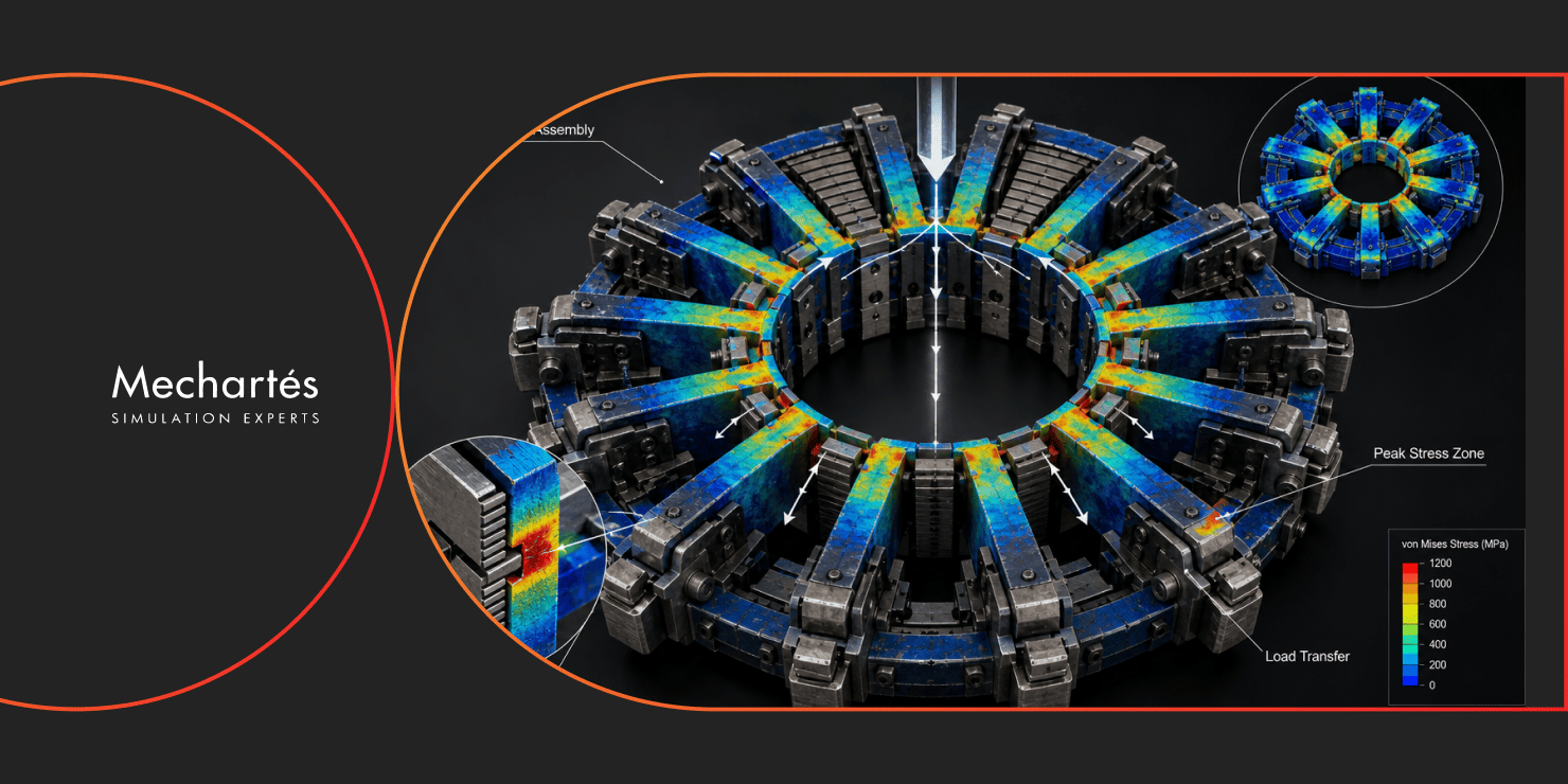
A flush-mounted spider assembly doesn’t draw much attention on a drawing sheet, but put it through FEA, and it’s a different story. The assembly we recently worked on had ten sets of interconnected components, each made up of a rib, a slip, and four dies, all operating under demanding load conditions in critical drilling service. Given that level of complexity and how much rides on this equipment in the field, conservative assumptions weren’t going to be enough.
Ten sets of interconnected parts sounds manageable until you consider how they interact. Each rib, slip, and set of four dies doesn’t behave in isolation. Load passes between components, contact surfaces shift under pressure, and how one part responds changes what the next one experiences. Hand calculations give you a starting point, but they tend to treat components as independent, and that’s not how an assembly under load actually behaves.
That’s where finite element analysis comes in. Instead of relying on broad safety margins to cover what hand calculations can’t capture, FEA lets the model carry the geometry, contact behavior, and load combinations, so you can see where the assembly genuinely sits under stress and where it has margin to spare.
The flush-mounted spider sits at the center of the operation, gripping the drill string and holding it steady under load. In this case, the assembly was made up of ten interconnected sets, each carrying its own rib, slip, and four dies. That works out to 40 dies across the assembly, each one a contact point where load transfers.
Multiply that across the load combinations the assembly sees in service, and a piece-by-piece conservative approach starts to look thin.
For this project, we evaluated each component (the ribs, slips, and dies) under multiple load combinations rather than a single worst-case scenario. A design that holds up under one combination can still be vulnerable under another, and that’s exactly what a single design-case check won’t surface.
Realistic boundary conditions and contact interactions went into the FEA model as well. Components in a spider assembly aren’t rigid bodies bolted together. They sit against each other and transfer force through contact surfaces that open and close depending on what’s happening elsewhere in the assembly. Modeling that properly, rather than simplifying it away, is what separates a model that looks right from one that actually tells you something.
That work let us map load paths through the assembly, pinpoint the locations carrying the highest stress, and confirm the assembly could safely withstand its operating conditions across every load combination evaluated.
On a project like this, FEA goes well beyond producing stress contours to file away. For a complex assembly with components that interact the way this one does, the value shows up in a few distinct ways.
The most immediate value is catching where failure is most likely to start, including failure modes that hand calculations don’t surface. Contact-driven stress concentrations and load redistribution, when one component shifts under pressure, only show up when the assembly is modeled as a whole rather than analyzed part by part.
Catching it early matters because the alternative is finding it during physical testing, or after fabrication. A thorough FEA case study approach cuts down both the number of physical testing cycles needed and the rework that follows when something gets flagged late.
FEA also leaves behind a documented record of the analysis behind each engineering decision, rather than conservative margins that a team simply hopes will hold. For equipment this critical, that record carries as much weight as the result itself.
It also means multiple load scenarios can be checked before anything reaches fabrication, rather than designing around one assumed case and hoping the others don’t show up in service.
Finding a design problem after fabrication almost always costs more than the analysis that would have caught it beforehand. Once parts are cut, machined, and assembled, a stress concentration missed at the design stage turns into a rework job, a schedule delay, and sometimes a safety question raised at the worst possible time.
Most clients who’ve been through that once don’t need much convincing to run FEA the next time. The cost of the analysis is small compared to the cost of finding out the hard way that an assumption didn’t hold.
For critical drilling equipment like this flush-mounted spider assembly, FEA isn’t an optional add-on late in the design process. It’s what gives a team the confidence to go into fabrication without caveats. Not a model sitting in a report, but a clear picture of how the assembly actually behaves under the loads it’ll see in service.
At Mechartes, our FEA and structural analysis work covers this kind of validation for critical equipment across oil and gas and other demanding industries, from mapping load paths to confirming a design before fabrication. If you’re working on critical drilling equipment and need a structural validation your client will accept, get in touch.