When a single pipe feeds sixteen air cooler bays, the expected outcome is relatively equal flow distribution across all outlets. Most piping layouts are designed with this assumption in mind. However, when the fluid isn’t just vapor, and when corrosion protection depends on a small amount of injected wash water reaching every single bay, this assumption can lead to significant operational problems.
In many refinery air cooler systems, wash water is injected upstream into the process stream to dissolve salts that would otherwise deposit in the cooler tubes and accelerate corrosion. The water injection rate is typically small relative to the total flow, which creates a unique distribution challenge.
Because the water fraction is low by volume, it doesn’t behave like the mainstream. It travels as dispersed droplets, and those droplets respond to flow dynamics differently than vapor. If the piping geometry creates any preferential flow path, the liquid phases (including wash water) will follow it. Some cooler bays receive excessive amounts while others receive almost none.
The consequences aren’t immediately apparent. Corrosion doesn’t announce itself right away. But over time, the bays receiving insufficient wash water begin to degrade faster, leading to tube failures, unplanned downtime, and expensive repairs.
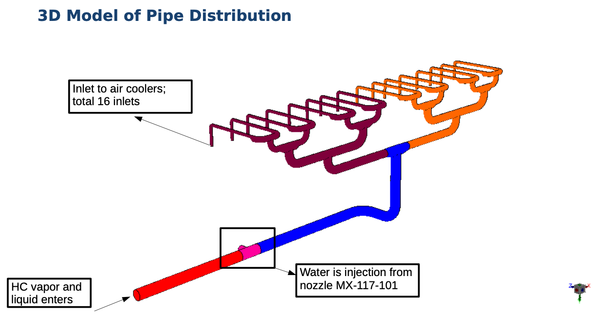
The reactor effluent stream in this project carried a mixture of vapor and liquid hydrocarbons, with wash water being injected at a single upstream nozzle. From that injection point, the piping branched progressively through bends and tees until it reached sixteen individual air cooler inlets, arranged on two sides.
The design question was direct: does equal water distribution actually reach each cooler bay?
The modeling challenge lies in the uncertainty around droplet formation. At the design stage, predicting exact droplet sizes is difficult because droplet formation depends on injection velocity, fluid properties, and pipe geometry. Rather than assume a single droplet size, we ran a sensitivity analysis across a range of droplet sizes for both the liquid hydrocarbon and the wash water. This approach allowed us to understand how sensitive the distribution was to this uncertainty.
We built a CFD model of the complete pipe network, from the main inlet through the injection nozzle all the way out to the sixteen air cooler inlets. The geometry was taken directly from the 3D plant model, ensuring that bends, tees, and riser sections were all represented accurately.
The modeling approach treated the vapor as the continuous (primary) phase, with liquid hydrocarbon and water modeled as discrete droplet phases carried within it. For each liquid phase, multiple simulations were run at different droplet sizes to build up a picture of how the distribution changes with droplet diameter.
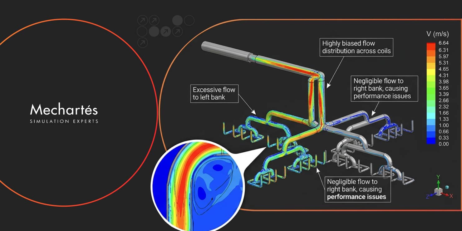
The vapor distribution across the sixteen outlets was reasonably uniform. There was some variation between inlets, with slightly more flow going to one side than the other, but nothing that would raise serious operational concerns. Bends and tees introduced some asymmetry, which is expected in any piping network.

The liquid phases, however, told a very different story.
Even at small droplet sizes, the liquid hydrocarbon was heavily skewed toward one side of the network. As droplet size increased, the imbalance grew sharply. At larger droplet sizes, one entire side of the air cooler array received essentially no liquid hydrocarbon at all.
The wash water distribution was even more problematic. The maldistribution was severe across all droplet sizes tested. Even at the smallest droplet sizes, the variation in water flow across the outlets was extreme. Some inlets were receiving several times more water than others. At larger droplet sizes, water reaching the coolers on one side dropped to near zero.
The primary driver of this maldistribution is the turbulent flow patterns created at pipe elbows and tees. As the vapor stream navigates bends in the piping, it develops swirling and radial velocity components. Small droplets get swept along and become concentrated on one side of the pipe cross-section before the flow even reaches the first distribution tee. Once this initial bias is established, subsequent splits compound rather than correct the imbalance.
The velocity in the wider distribution headers was also quite low, which created recirculation zones. Larger droplets tend to accumulate in these dead zones rather than staying entrained in the flow, further compounding the maldistribution.

The findings pointed to several potential improvements, each targeting different aspects of the distribution problem.
For vapor maldistribution, extending the straight pipe runs after bends and tees provides more length for the flow to recover before the next split. This is a relatively straightforward layout modification that can be implemented during detailed design.
For liquid phase maldistribution, layout changes alone aren’t sufficient. The turbulence-driven bias is introduced upstream and persists through the network. Internal flow conditioning devices at key elbows and tees can help break up the swirling patterns and redistribute the droplets more evenly across the pipe cross-section. Perforated distribution elements in the riser sections are another option.
The most impactful recommendation was to rethink the wash water injection strategy entirely. Rather than injecting water at a single upstream location and relying on the piping geometry to distribute it, the preferred approach is to install individual injection nozzles closer to each air cooler inlet. Each cooler receives a controlled, independent supply, which eliminates the distribution problem at its root.
Any layout modifications do add pressure drop to the network, which needs to be accounted for in the hydraulic design.
The piping arrangement for distributing flow to multiple parallel air cooler bays often appears symmetric on paper. An engineer reviewing the isometric drawing sees equal branch lengths and a balanced layout. However, the actual flow behavior accounts for bends, tees, velocity gradients, and momentum effects that aren’t apparent from geometry alone. When dealing with a multiphase stream where one phase is present in small quantities, the conventional assumption of uniform distribution can fail without obvious warning signs.
CFD provides the ability to test these assumptions before fabrication, when changes are relatively inexpensive. Discovering that half the air coolers are receiving inadequate wash water during commissioning represents a significantly different cost and schedule impact compared to identifying the issue during a simulation study.
For refinery and petrochemical projects involving multiphase streams distributed across parallel equipment, this type of analysis provides value early in the design phase. The design modifications recommended here aren’t complex or costly in isolation; the expensive part is discovering the need for them after the plant is built.
At Mechartes, we’ve completed numerous multiphase flow and pipe distribution studies for oil and gas and petrochemical facilities across the Middle East and beyond. Our CFD analysis capabilities help identify distribution issues during the design phase when modifications are most cost-effective.
If you’re dealing with similar distribution challenges in your process piping systems, contact us to discuss how simulation can help you identify and resolve these issues before they impact operations.