We recently completed a CFD for data center project using Cadence Reality DC Design, a platform we’ve been integrating into our workflow over the past year. The study covered both normal operating conditions and a cooling unit failure scenario, and the results were detailed enough that it seemed worth documenting.
For context: Mechartes has been doing CFD and simulation work for over 20 years across 20,000+ projects. Data centers have become a meaningful part of that portfolio, particularly in the Middle East, where ambient temperatures regularly hit 45°C and rack densities keep climbing with AI infrastructure buildouts. The thermal margins are tighter in this region than most others, which is part of why the modelling has to be thorough.
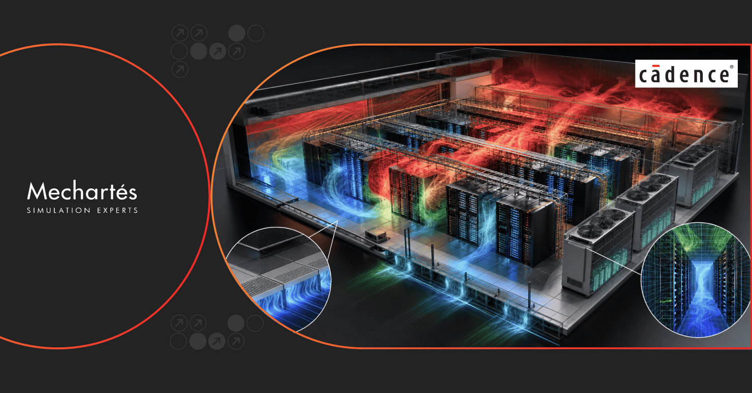
Data center airflow doesn’t behave the way the drawings suggest. Underfloor pressure gradients aren’t uniform, perforated tiles don’t deliver what the specification says under real conditions, and hot exhaust recirculates in patterns that only become visible at the individual rack level. You don’t find these things through hand calculations or rule-of-thumb sizing.
CFD for data center environments lets you simulate those conditions before the equipment goes in. Rack-level heat distribution, layout change impacts, air leakage and bypass paths, failure mode behaviour, day-one performance under partial load, all of it can be tested and adjusted in the model before anything is built.
Cadence Reality DC Design is worth mentioning specifically here. It’s built for data centers, not a general CFD solver adapted for them, and that distinction shows in how the data center-specific physics get handled.

The objective was to verify, through CFD for data center simulation, whether the proposed HVAC system could maintain stable operating conditions across the data hall. That meant checking airflow uniformity, server inlet temperatures against ASHRAE’s 18°C to 27°C recommended range, hot spot risk at rack inlets, and hot aisle behaviour.
We didn’t just run the design-day case. The study evaluated both N and N+2 cooling configurations, along with a degraded mode in which only N units were operational. It also covered a transient failure scenario at full data hall load, specifically, the complete failure of the chilled water system.
The 3D model covered the full data hall: server racks and containment structures, cable trays, lighting, structural supports, and the false ceiling with its return air path and cooling unit.
The level of detail matters more than it might seem. In CFD for data center work, a simplified model can produce plausible-looking results while missing the specific failure modes you need to find. Our models include air leakage paths, bypass flows, actual rack dissipation profiles rather than nameplate values, and physical obstructions like cable tray runs and blanking panel gaps. These are the things that drive real behaviour.

The first steady-state run showed uneven airflow distribution with hotspots across the data hall. Some zones were under-cooled, not critically, but enough to produce hot spots at rack inlets under normal operating load. Left unaddressed, those spots would have shown up during commissioning or, worse, post go-live.
We iterated on the design, adjusting the cooling unit configuration, airflow rates, and redistributing airflow across cold aisle zones. The optimised configuration delivered uniform distribution across the hall, no hot spots, and server inlet temperatures within design limits at all rack positions.
The client had a validated layout before construction, rather than discovering the problem on-site.
The failure scenario involved the complete failure of the chilled water system at full data hall load. The FWU cooling was briefly offline while the FWU fans, which are UPS-backed, continued operating. The question was straightforward: how long do server intake temperatures stay below the 40°C threshold during this period?
The result: server intake temperatures remained within the 40°C limit for up to 2.5 minutes following full chilled water failure.
That number doesn’t come from a spec sheet. It’s the kind of result that changes how a team thinks about which redundancy configuration is actually sufficient, and how fast monitoring and response protocols need to work for that configuration to mean anything.
The steady-state analysis caught real layout issues that would have been expensive to address post-construction. The transient analysis puts a number on the failure window in a way that informs actual decisions, not just ticks a compliance box.
Both are things you can only get from CFD for data center simulation done at the right level of detail. Cadence Reality DC Design performed well across both analyses. The accuracy on the transient side in particular gave us confidence in the results, and we’re now using it for data center projects alongside our existing simulation tools.
The steady-state analysis caught layout issues that would have been expensive to find post-construction. The transient analysis put a specific number on the failure window, 2.5 minutes, which is the kind of result that changes how teams think about redundancy configurations and response protocols, not just compliance documentation.
Both outcomes came from modelling at the right level of detail. Simplified models can produce plausible-looking results while missing the failure modes that actually matter. That’s the distinction that makes the approach worth doing properly.
At Mechartes, our data center simulation work covers thermal performance validation, failure mode analysis, and layout optimization, primarily for projects in the Middle East where the thermal margins leave little room for guesswork. If you’re at the design stage and want to understand what a CFD study for your data center project typically involves, get in touch.