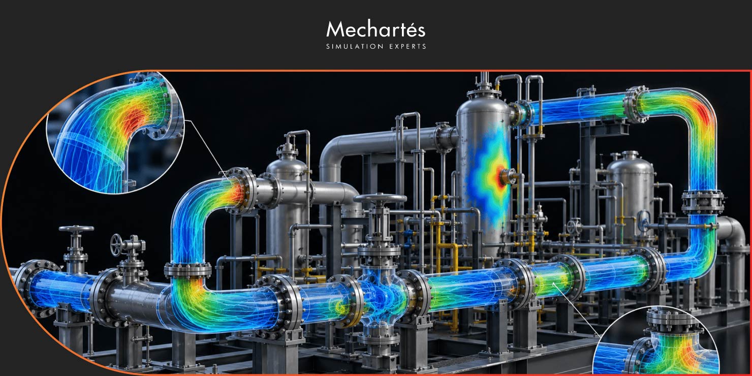
Piping systems in oil and gas, petrochemical, offshore, and process facilities deal with high-pressure, high-velocity fluids around the clock. Most of the time, that’s fine. But when conditions combine in the wrong way, vibration can build up in the system until something gives.
The two most common vibration failure mechanisms in process piping are acoustic induced vibration (AIV) and flow-induced vibration (FIV). Both are manageable, but only when they’re identified at the right stage.
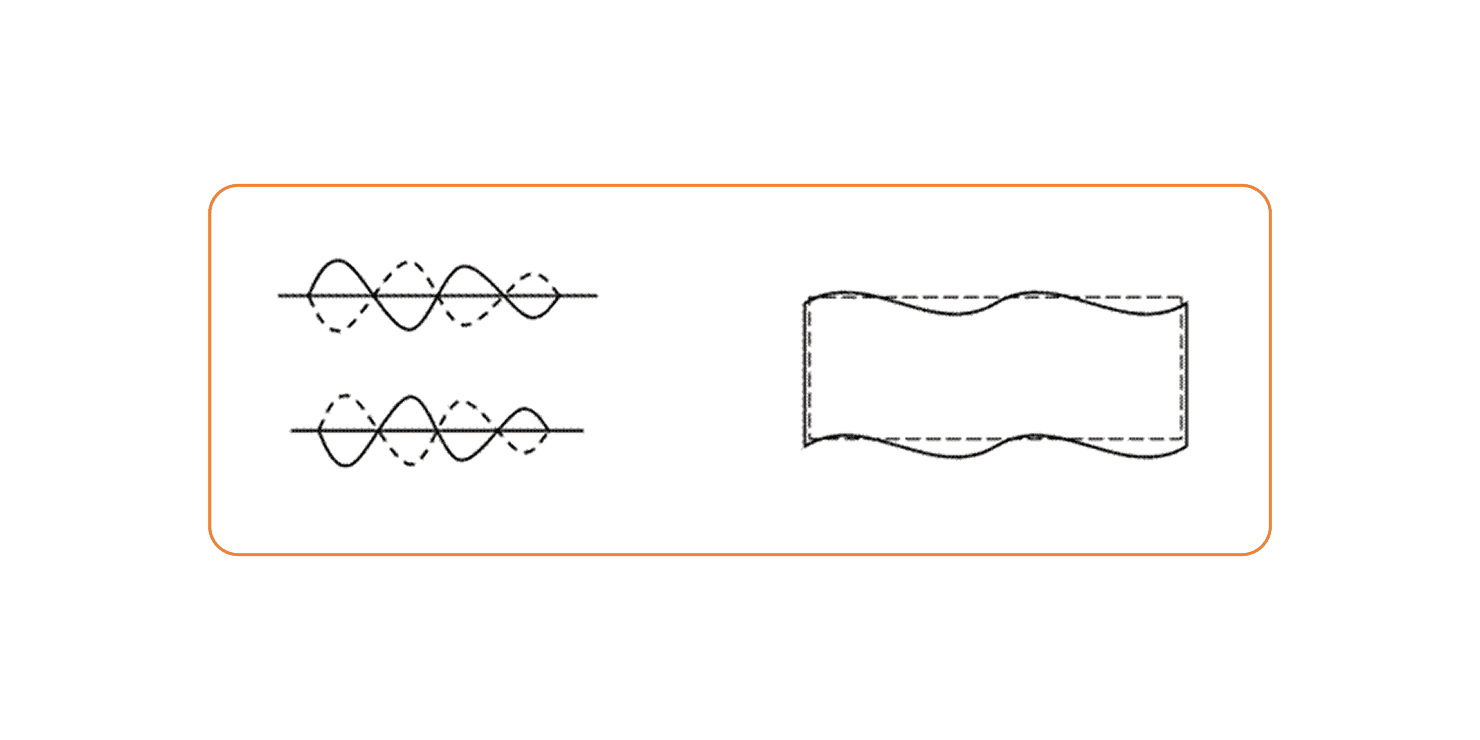
Acoustic induced vibration in piping occurs at pressure-reducing devices in gas or vapor service. Pressure relief valves, control valves, compressor anti-surge valves, choke valves, and orifice plates can all generate high-frequency broadband acoustic energy when gas passes through them. The amplitude of that energy scales with flow rate and pressure drop.
The acoustic energy doesn’t just travel through the gas. It excites the pipe wall itself, driving what’s known as a shell flexural mode of vibration. At circumferential discontinuities on the pipe wall, small-bore connections, fabricated tees, and welded pipe supports, the resulting dynamic stress concentrations can be high enough to initiate fatigue cracks.
The standard assessment approach uses sound power level (PWL). Piping systems with a PWL above 155 dB require detailed assessment and redesign in line with the Energy Institute guidelines. The urgency matters too: fatigue failures at small-bore branches have been documented within minutes to hours of first operation. That’s not a figure of speech, and it’s the main reason AIV assessment has to happen at the design stage.

Flow-induced vibration works through a different mechanism. FIV is generated by turbulent flow: two-phase conditions, flow discontinuities, and other instabilities. The excitation concentrates at lower frequencies, and the dominant effect is displacement of the piping system in the longitudinal and transverse directions. Pipe wall flexure isn’t the primary concern.
Severe FIV can damage pipe supports. Where support damage goes undetected, the risk profile of the line changes in ways that aren’t always visible from a routine inspection.
Momentum flux, the product of fluid density and velocity squared, determines how much kinetic energy a fluid imparts to the pipe. Because liquids are considerably denser than gases, liquid-dominant and two-phase flow lines are more susceptible to flow-induced vibration in piping than comparable gas lines at the same velocity.
Like AIV, FIV follows the Energy Institute screening framework. The assessment approach is the same; the excitation mechanism is different.
The EI Guidelines give engineers a structured screening method for both AIV and FIV risk, written to be accessible without specialist vibration knowledge. The output is a Likelihood of Failure (LOF) score: a relative measure of how susceptible a given system is to vibration-induced fatigue.
The recommended actions by LOF band:
Where screening flags elevated risk, detailed analysis and mitigation planning follow.
When a system is identified as high risk, there are well-established options for reducing it. The right choice depends on the excitation source, the geometry, the operating conditions, and how far along the project is.
For acoustic induced vibration in piping, mitigation generally targets either the source or the pipe’s structural response to it. Using a higher pipe schedule lowers the diameter-to-thickness ratio, which reduces the pipe wall’s susceptibility to shell flexural vibration. Low-noise trim inside the pressure-reducing valve reduces the acoustic energy generated at the source. Adding line length between the valve and the nearest high-risk branch connection reduces the energy arriving at that location.
Smooth branch fittings minimize stress concentration at connection points. Full wrap-around pad supports on welded supports do the same. Stiffening rings and clamp-on supports can provide local rigidity at particularly vulnerable locations.
For flow-induced vibration in piping, increasing system rigidity is usually the first step. Guide and line-stop supports reduce the pipe’s tendency to displace under flow loading, which directly lowers the likelihood of fatigue failure.
Where the layout allows, increasing the pipe diameter reduces fluid velocity and the corresponding momentum flux. Reducing the number of turbulent sources like elbows and reducers can help where changes are feasible. Viscous dampers, snubbers, shock arrestors, and sway braces are also options where structural modifications are constrained.
AIV and FIV are understood risks with documented mitigation paths. The challenge is identification timing. Catching these issues at the design stage means targeted changes to pipe schedule, valve selection, branch configuration, or support layout. Finding them after the fact usually means retrofit work, and retrofit work in process piping is almost always more disruptive and expensive.
At Mechartes, our vibration analysis team carries out AIV and FIV assessments, risk screening, detailed engineering analysis, and mitigation recommendations for oil and gas and process facilities worldwide. If you’re seeing vibration concerns on existing systems, or want to build these checks into a new project, get in touch with our team.
Acoustic induced vibration (AIV) is a high-frequency vibration phenomenon caused by acoustic energy generated at pressure-reducing devices, such as control valves, relief valves, choke valves, and anti-surge valves, in gas or vapor piping systems. The energy excites the pipe wall in a shell flexural mode, concentrating stress at small-bore connections, fabricated tees, and welded supports.
AIV is acoustically driven and high-frequency. It’s specific to gas service and originates at pressure-reducing devices. FIV is driven by turbulent fluid flow and tends to produce low-frequency excitation. It displaces the piping system; the pipe wall response is fundamentally different. Both can cause fatigue failure, but through different mechanisms and in different types of lines.
Faster than most people expect. Fatigue failures at small-bore branch connections due to acoustic induced vibration have been documented within minutes to hours of a system first coming into operation. This is why AIV has to be assessed at the design stage. Waiting for field symptoms is too late.
The Likelihood of Failure (LOF) score is a risk-screening output from the Energy Institute’s Guidelines for the Avoidance of Vibration Induced Fatigue Failure in Process Pipework. It measures relative susceptibility to vibration-induced fatigue. A higher score means more risk; the guidelines specify what action to take at each band. Higher scores indicate greater risk, and the guidelines define specific assessment and remediation actions for each LOF band.