
Piping systems connected to reciprocating injection pumps are critical to the reliability and safety of process installations. When excessive pressure pulsations and vibrations run through these systems, the consequences extend far beyond immediate discomfort. You’re dealing with mechanical fatigue, acoustic noise, cavitation, and potentially serious damage to vital equipment.
The impacts don’t stop at the equipment itself. Flow meters and control instruments can lose accuracy, throwing off process control across the board. Left unaddressed, these dynamic interactions compromise operational efficiency and lead to costly downtime.
For facilities running MEG (Monoethylene Glycol) injection systems, managing pulsation and vibration isn’t optional. It’s fundamental to maintaining reliable operations and protecting critical infrastructure.
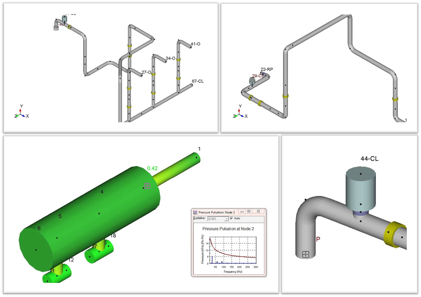 Sample images- Modelling of Suction and Discharge piping network
Reciprocating pumps generate pulsations by their very nature. Each stroke of the plunger creates pressure waves that propagate through the piping network. When these pulsations aren’t properly controlled, they create a cascade of problems.
Pressure variations can trigger liquid hammer conditions that stress piping components beyond their design limits. Vibrations from unbalanced forces can lead to fatigue failures in pipes, supports, and connected equipment. Cavitation risks increase when pressure fluctuations drop below the fluid’s vapor pressure. And control instruments struggle to maintain accuracy when measuring pulsating flow.
Industry standards like API 675 exist specifically to address these challenges in reciprocating pump installations. The standard provides methodologies for analyzing pulsation behavior, sizing dampening equipment, and designing piping systems that maintain safe operating conditions.
API 675 specifies two distinct design approaches for controlling pulsation and vibration, and understanding which one to use matters for getting results that work.
This approach determines required pulsation dampener volume based on peak pressure pulsation limits. It also evaluates the minimum critical pipe length needed to avoid acoustic resonance within the piping network.
Design Approach 1 works well for systems with stable operating conditions and simpler layouts. The calculations are more straightforward, and the method provides adequate control for many standard applications.
Design Approach 2 focuses on pulsation control through pressure control devices combined with mechanical analysis. This is the approach you’d typically use for critical pump and piping systems, multiple pumps running in parallel, and applications involving variable speeds, multiple fluids, or variable operating conditions.
This approach requires more detailed modeling but provides greater confidence in system performance under complex operating scenarios.

At Mechartes, we recently performed pulsation analysis for a MEG injection pump system using Bentley PULS software following API 675 Design Approach 2. The project involved evaluating pressure variations, liquid hammer potential, cavitation risk, and pipeline vibration loads.
The analysis covered one operating case: one of two MEG injection pumps running at rated speed with the other on standby. We modeled both the suction and discharge piping networks based on 3D models and isometric drawings.
The suction line ran from the MEG injection storage tank to the pumps, while the discharge line connected the pumps to the discharge header. All relevant geometric details were incorporated into the model, including pipe lengths, fittings, support locations, and configurations.
Getting accurate pulsation analysis results requires detailed system and process information. For this project, we needed mechanical and drawing data (P&IDs, pump skid general arrangement drawings, pipe material specifications, support types and locations), fluid properties (density, viscosity, bulk modulus, operating pressures, temperature, flow rate), pump parameters (stroke length, plunger diameter, number of cylinders, rated RPM, NPSHA and NPSHR values), and ancillary equipment details (PSV settings, suction and discharge dampener types and capacities).
The analysis followed a structured approach. We evaluated peak-to-peak pressure variations to predict liquid hammer conditions and compared results against API 675 limits. Vibration and harmonic loads (shaking forces) were determined along both suction and discharge lines.
Mechanical vibration analysis verified that pipeline natural frequencies didn’t coincide with pump operating frequencies. When they do align, you’re asking for resonance problems. We used harmonic loads to identify regions of high stress and deflection in the piping, then developed recommendations for modifications to maintain API 675 compliance.
Based on the analysis, we identified specific issues and provided targeted recommendations to bring the system into compliance.
The existing 15L pulsation dampener on the suction side was sufficient to control pulsation levels in the suction piping network. However, the existing 15L dampener on the discharge side wasn’t adequate.
We recommended installing 47.5L dampeners near each pump on the discharge side. This capacity increase would maintain pulsation pressures within API 675 allowable limits and prevent the problems we identified in the analysis.
The analysis showed that additional supports and modifications to existing supports were needed to maintain the critical 20% separation margin from significant pump frequencies. Without this separation, the system risks resonance conditions that amplify vibrations.
Design modifications, particularly additional supports and changes to existing supports on the discharge piping network, were recommended to reduce stresses and deflections. Without these changes, the system faces potential fatigue failures over time.
Effective pulsation and vibration analysis isn’t a checkbox exercise. It’s essential for ensuring the reliability, safety, and longevity of mechanical systems handling critical injection processes.
By combining pulsation control, mechanical vibration assessment, and adherence to industry standards, facilities can minimize damage risk, improve system performance, and extend equipment life. These practices are particularly critical for pumps, compressors, and other reciprocating machinery where uncontrolled pulsations and vibrations lead to fatigue, cavitation, or operational disruptions.
At Mechartes, we bring expertise in pulsation and vibration analysis for reciprocating pumps and compressors, following API 674, API 675, and API 618 standards. Our solutions help ensure systems operate safely, efficiently, and reliably under complex operating conditions.
Ready to discuss pulsation analysis and vibration mitigation for your critical pump systems? Contact us to explore API-compliant solutions for your facility.