At Mechartés, we have been working on several Data Center Projects across the globe providing consultancy services for the Internal Air Flow Distribution study, and External Air Dispersion Modelling for the yard and Mechanical Rooms.
In this article, I would like to share our learnings and insights from a CFD Analysis we carried out for the Diesel Rotary UPS System (DRUPS) Room for one of our clients.
So let’s dive right in!
1.Introduction
Diesel Rotary Uninterruptible Power Supply Devices (DRUPS) combine the functionality of a battery-powered or flywheel-powered UPS and a diesel generator. When the main electricity supply fails, stored energy in the flywheel is released to drive the electrical generator, which continues to supply power without interruption. At the same time (or with some delay of a few seconds to prevent the diesel engine from starting at every incident), the diesel engine takes over from the flywheel to drive the electrical generator to make the electricity required.

Heat generation from the DRUPS are high and ventilating the room is necessary to avoid any tripping of the equipment and provide safe working condition. CFD assist engineers in designing the ventilation study and to see if there is any hot spots/re-circulation and to maintain desired temperature.
2. Objective
The main objective of the CFD analysis for the Project owners/contractors/design consultants is to check the following,
i. Proper Air circulation with no dead regions.
ii. Average temperature of less than 55°C is maintained or not in the DRUPS room.
iii. Temperature at the alternator is within the proximity of 50°C or not.
iv. Temperature at the inlet of the engine is within the proximity of 55°C or not.
CFD analysis was carried out for different working conditions with peak heat load conditions.
3. Modelling
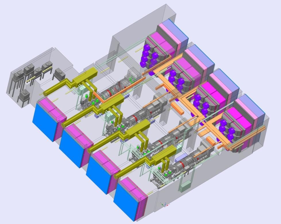
As per the inputs and design drawings received a detailed 3D modelling of the room was prepared along with the HVAC inputs in the CFD Software.

The obstructions inside the room including all the service pipes, bus bars, cable trays, lighting fixtures were modelled. Detailed modelling of the intake and exhaust air openings along with the attenuator, dampers, filter, louver with the fans were modelled.
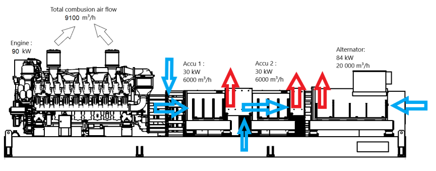
The complex and important part of the analysis is to model the DRUPS Unit which was carried out as per the 3D Model received from the client.
Appropriate boundary conditions in terms of Intake, Exhaust air flow rates, pressure drop, heat loads from equipment were applied. Heat load from the DRUPS unit were applied for each parts i.e. engine, accumulators & alternator.
4. Conclusion
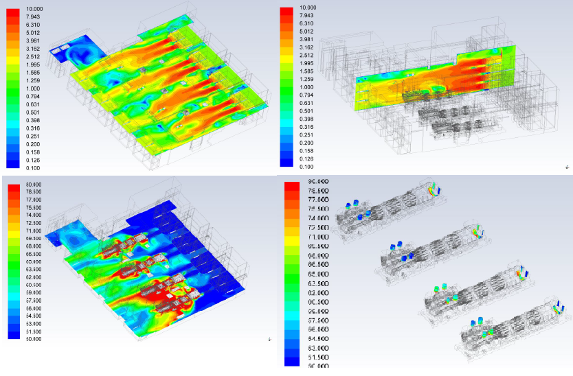
Upon completion of the 3D model , CFD steady state simulations was carried out for the DRUPS room for different scenarios to study the velocity, temperature and pressure profiles. From the analysis it was observed that the average velocities obtained at various heights were in the range of 1.1 m/sec to 1.5 m/sec.

It was observed from the study that there was high temperatures of up to 61°C was observed near the DRUP Units. This was mainly due to the positioning of the propeller fans which was causing the ambient air to move above the DRUPS unit and blocking the upward movement of the hot air from the units surface.
Recommendations and a revised study were implemented with changes in reduced fan velocity, and the fans were placed at lower heights to meet the design objective.
We at Mechartés are always focused on providing accurate simulation results with a professional and engineering approach. Our biggest strength is our team of young and passionate engineers who work very well as a close-knitted team.
Feel free to share your comments and observations at srihari@mechartes.com or drop me a message here on LinkedIn. Comments are also welcome!
In the next article, I will be sharing all about the study we carried out to assess the impact of the hot air discharged from the DRUPS unit and the mechanical units in the corridor area.

