1. Introduction
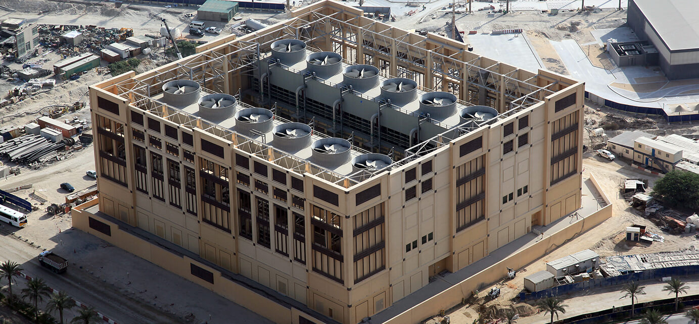
The performance of cooling towers can be adversely affected by insufficient intake of fresh air and the spacing between the cooling towers. This can lead to re-circulation of hot air into the cooling tower inlets from the outlet of the cooling tower.

CFD Analysis can assist engineers to evaluate the performance of the cooling tower during the design stage / construction stage and also to take necessary mitigative measure to eradicate such issues.
It can also be used during the operational stage to mitigate any issues in the operation of the Cooling Tower.
Most often the cooling towers are placed the nearby buildings and a very most important criteria to not allow the cooling tower plume to travel to the nearby buildings to impact the occupants which can also cause diseases including Legionella. So, it has become mandatory to study the impact of the plume during the design stage and take necessary actions.
2. Objective
The main objective of the CFD analysis for the Project owners/contractors/design consultants is to check the following:
-
To study whether the “hot humid air rejected from each cooling tower fan outlet” is entering into
the “inlets of the cooling tower” or not, and if so, how severe is the re-circulation of air is & what
is % of re-circulation.
-
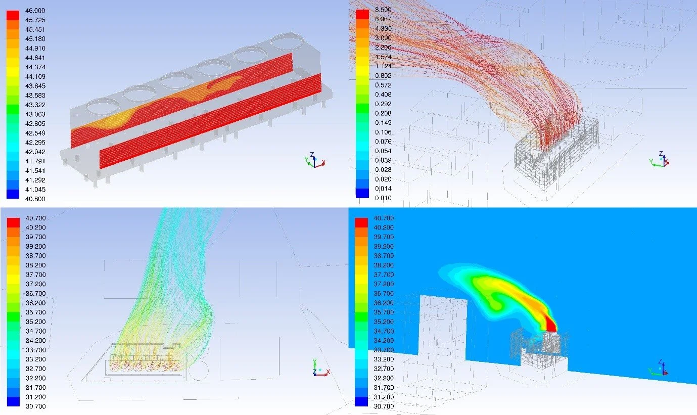
To study the velocity, temperature & relative humidity profiles around the Cooling Towers.
-
To study the impact of the Plume on the nearby occupant locations.
3. Modelling
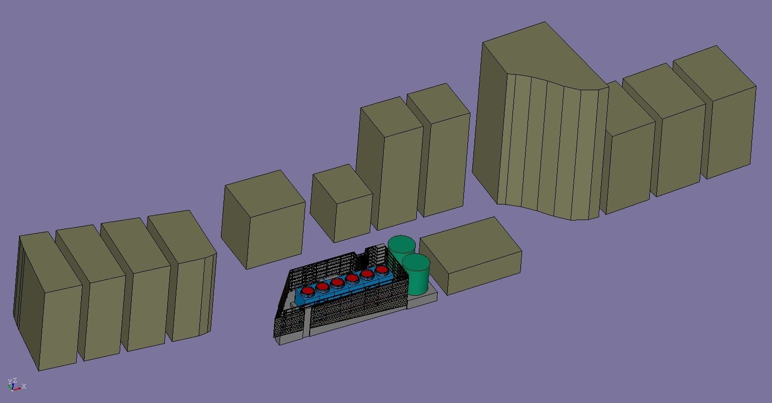
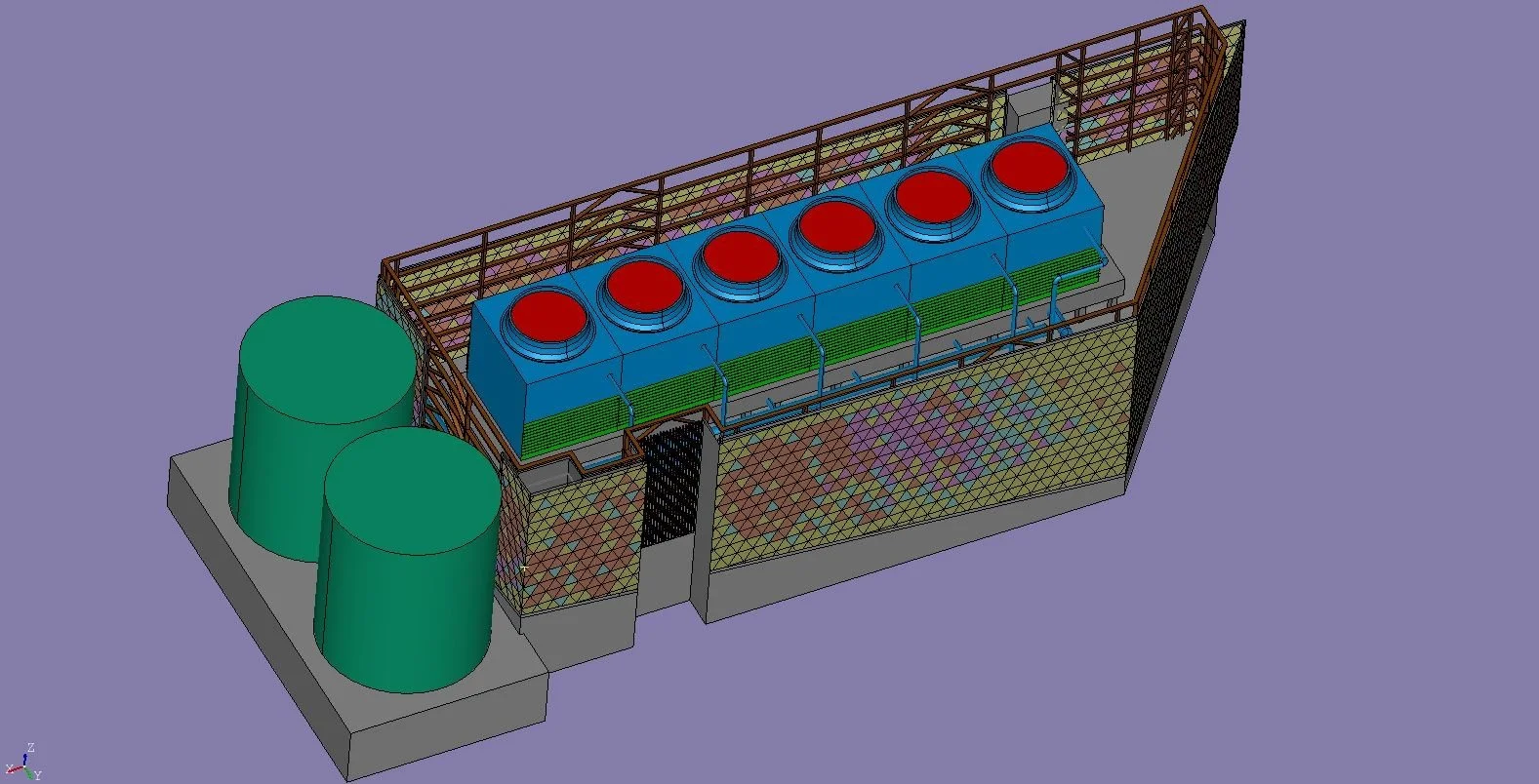
Per the inputs and design drawings received, we prepared a detailed 3D model of the complete cooling tower plant in the CFD Software.

A CFD Wind tunnel is created by modelling the nearby buildings. In the Cooling tower building all the obstructions including the major pipes, wall obstructions, equipment’s were also modelled along with the Louver details.
Appropriate boundary conditions, including the intake, discharge temperature and velocity from the cooling towers were considered for the study. The wind and ambient conditions were chosen for the work per the project requirement and site location.
4. Conclusion

Upon completion and approval of the 3D model report, a steady-state CFD Simulation was performed to study the velocity, Dry Bulb and Wet Bulb temperature, Relative humidity, % of re-circulation on each inlets, Plume travel towards the nearby building were studied.
It was observed from the study that there was a considerable increase in temperature at the inlets of the cooling towers which had an impact on the performance.
The recirculation calculations found that nearly 5 to 35% of air recirculated resulting in increase in Wet bulb temperature above the design objective. This was mainly due to the movement of hot air from outlets towards the inlets of the cooling tower outlets. However, it was observed that there was no plume travel towards the occupant location and the plume dissipated with the ambient air in the plant.
5. Recommendation
To prevent the effect of high-temperature outlet discharge air moving toward the inlets of cooling tower, revised CFD studies were conducted with the installation of stacks at the cooling tower discharge and canopies between the cooling towers were suggested.
The site had limitation to unable to move the cooling towers and provide more spacing between them so the above recommendations were suggested. Multiple iterations were carried out with the modifications which clearly showed a considerable decrease in the re-circulations improving the performance of the cooling tower.

