A hospitality client brought us in to look at a rooftop plant where something didn’t add up. Three air-cooled chillers had been installed and commissioned, all three were running, and the building still couldn’t meet its cooling demand. Through the hotter parts of the day, the units kept tripping. On paper, the design looked fine, and the equipment had been specified and installed correctly. The problem wasn’t in the chillers themselves. It was in the air moving around them, and that’s where CFD analysis came in.
The setup was straightforward enough. Three air-cooled chillers sat on the hotel rooftop, enclosed on almost all sides, a common aesthetic requirement in hospitality projects. Fresh air came in through side louvers, and discharge air left through a meshed opening at the top of the enclosure, with limited free area.
None of this looked unreasonable on a drawing. Enclosures like this are standard practice, and the arrangement met the usual visual requirements without raising obvious flags on paper. It was only once operations started that the performance issues set in, with the chillers struggling to keep up during the hottest parts of the day.
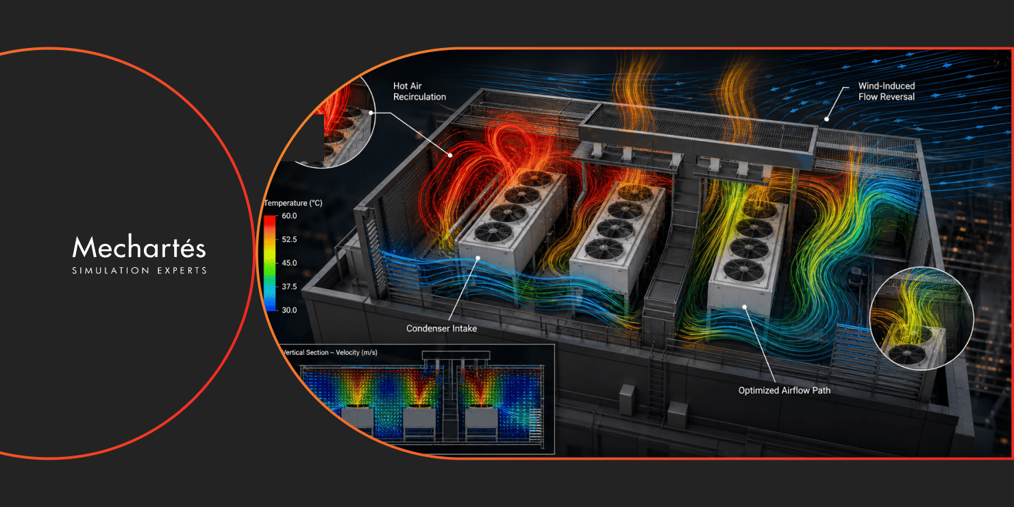
The Mechartes team started by reviewing the original design conditions and the constraints of the site itself. That meant looking at chiller spacing and placement, the discharge air temperature coming off the chillers (close to 60°C), the available intake air paths, local ambient weather and wind conditions, and the geometry of the roof enclosure and its ventilation openings.
One thing stood out early. The chillers were dealing with significant hot air recirculation. Instead of rejecting heat to the atmosphere, a large portion of the discharge air was getting trapped inside the enclosure and pulled straight back into the condenser inlets, derating the chillers’ performance.
Since the plant was already built and commissioned, the question wasn’t only what was causing this. It was whether a fix existed that could actually be implemented within the constraints of a finished site, and that’s where CFD analysis of the rooftop plant area came in.
The first phase of the CFD analysis looked at introducing discharge stacks above the chillers, aimed at directing the hot exhaust air upward and away from the intake zones.
The results showed a more complicated airflow picture than expected. Ambient wind moving across the rooftop was working against the upward stack discharge. Rather than dispersing into the atmosphere, the hot air was being pushed back down and recirculated into the enclosed plant area.
The numbers from this simulation made the scale of the problem clear. Condenser inlet temperatures exceeded 53°C, and more than 50% of the discharge air was recirculating straight back into the condenser inlets.
Based on these results, the most effective fix would have been a dedicated discharge plenum above the chillers, with the rest of the enclosure sealed. That arrangement would channel the hot discharge air directly away from the plant area, eliminate the recirculation path into the condenser inlets, and restore the intake-exhaust separation the chillers needed to operate efficiently.
From a pure engineering standpoint, this was the right call. But the client’s site constraints ruled out major rooftop modifications, so the plenum arrangement wasn’t something that could go ahead.
With the plenum off the table, the team worked with what the site allowed: a canopy arrangement between the chillers, and a revised stack configuration designed to direct the discharge airflow more effectively.
We ran a second CFD analysis on the revised geometry. Condenser inlet temperatures came down to around 50°C, and recirculation dropped to roughly 30%, a meaningful improvement on the more than 50% seen in the first round.
It wasn’t the full recovery a plenum would have delivered, but given the site constraints, it was the best outcome available.
Enclosed or screened equipment areas don’t behave aerodynamically the way open installations do. Wind interaction, high discharge air temperatures, limited ventilation paths, and tightly spaced equipment combine in ways that standard HVAC calculations don’t pick up.
For rooftop installations, especially where equipment is architecturally screened for aesthetic reasons, airflow behavior, discharge dispersion, and recirculation effects need checking at the design stage, before the enclosure design is locked in. Running CFD analysis earlier in this project would have flagged these risks before construction, when addressing them would have cost a fraction of what a post-commissioning fix requires.
At Mechartes, we’ve carried out CFD analysis and root cause investigations for chiller plants and rooftop HVAC systems, covering hospitality, commercial, and infrastructure projects. If your project involves an enclosed plant area, or you’d like to validate the airflow design before construction rather than after, get in touch.