Specifying the right CRAH units is necessary. It’s also not enough. Cooling capacity and airflow distribution are two different problems, and most data centre thermal issues trace back to the second one.
A data hall can have adequate installed cooling capacity and still develop thermal hotspots. The capacity is there; the cold air just isn’t reaching the rack inlets where it needs to be. Understanding why requires looking beyond equipment selection to how airflow actually behaves in the space.
Airflow distribution in a data hall degrades through a combination of factors, each individually small but collectively significant. By the time rack inlet temperatures rise above acceptable limits, several of these are usually working together.
Raised floor tiles control where cold air enters the hot aisle/cold aisle layout. Tiles in the wrong positions, or tiles with the wrong perforation percentage for the local underfloor pressure, deliver air unevenly across the row. Some rack inlets get more than enough; others get too little.
Containment systems work by separating cold supply air from hot exhaust air. Gaps in containment, whether at the top of racks, between rows, or through unfilled rack slots, allow hot air to mix back into the cold aisle. The effect is cumulative. Each gap is a small bypass, but together they raise the temperature at rack inlets above what the design intended.
Multiple CRAH units in a data hall don’t operate in isolation. Their pressure fields interact, and in configurations where units are positioned or balanced incorrectly, some zones receive airflow from multiple units while others receive very little. This pressure interaction is difficult to predict without modelling the full space.

A thermal survey of a data hall tells you that temperatures are too high. That’s useful as a starting point but not as a diagnostic tool. It tells you where the symptom is, not what’s causing it or how to fix it.
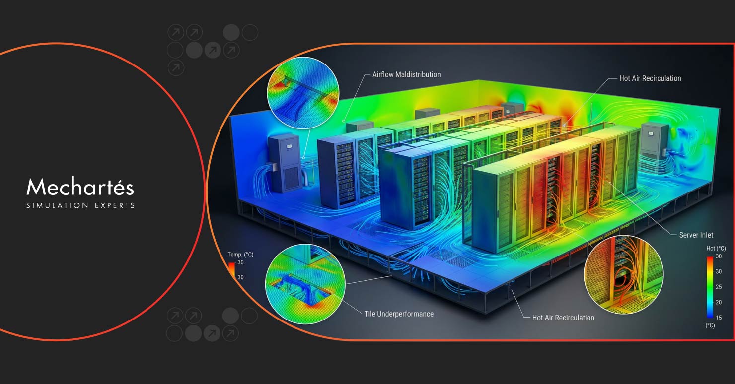
CFD analysis goes further. It shows which tiles are underperforming and why, where hot air is recirculating within the space, and what the sub-floor pressure distribution looks like across the full underfloor plenum. Importantly, it also lets you test a proposed fix before physically changing anything. That’s a meaningful difference when changes to a live data hall carry operational risk.
ASHRAE defines the acceptable server inlet temperature range as 15-32°C, and that requirement applies consistently across all load configurations and failure scenarios, not just steady-state normal operation.
Meeting this across all scenarios is a simulation problem, not a sizing problem. A CRAH selection exercise tells you whether you have enough capacity at design load. It doesn’t tell you whether cold air reaches every rack inlet uniformly, whether hot spots develop under partial load, or whether the design holds within limits during a cooling unit failure. Those questions need CFD to answer.
Across data centre projects in the Middle East and beyond, the internal and external airflow problems described above tend to appear together, and the findings from simulation are consistently more significant than the design assumptions anticipated.
On the internal side, data hall CFD studies regularly identify tile placement and containment gaps as compounding factors. A rack row that looks adequately served on the cooling layout often shows cold air bypass occurring before it reaches the intended inlets, with warm return air migrating into the cold aisle through containment gaps and open rack slots. The combined effect on inlet temperatures is typically larger than any single factor would suggest in isolation.
External yards tell a similar story. In one data centre yard study, Mechartes found recirculation at chiller and generator inlets ranging from 5 to 50% depending on wind direction and equipment position. That range is the important part: a yard that performs acceptably under one prevailing wind condition can see dramatically higher recirculation under another. Optimising for one condition without running multiple wind directions leaves a significant portion of the operating envelope unvalidated.
In a separate chiller yard analysis, recirculation was measured at 30.5 to 44.6% of discharged condenser air finding its way back to the chiller inlets. The inlet temperature was 6.12°C above ambient as a result, a meaningful COP penalty that hadn’t been anticipated from the layout. The corrections, adjusting louver opening sizes, modifying stack heights, and installing canopies between chillers, were straightforward once the simulation identified what was driving the problem. Finding the same issues after commissioning would have been a considerably more constrained exercise.
This is what CFD consistently delivers on data centre projects: not surprising findings in hindsight, but findings that were invisible without simulation.
The gap between a correctly specified cooling system and a correctly performing one comes down to airflow distribution. Identifying distribution problems after a data hall is commissioned and operational is a much more constrained and expensive exercise than finding them during design.
At Mechartes, our data centre CFD work covers data hall airflow and thermal analysis, external yard recirculation studies, and failure mode simulations across projects in the Middle East, the US, Europe, and Africa. If you’re at the design stage and want to validate distribution before the racks go in, get in touch with us now.