Pressure components in oil and gas facilities carry significant operational responsibility. A cap on a slug catcher might seem like a straightforward structural element, but when that component operates under high pressure, experiences thermal cycling, and must maintain integrity through years of service, design validation becomes critical.
Small design weaknesses in pressure-containing equipment can lead to catastrophic failures. The challenge is that many of these weaknesses aren’t apparent from geometry alone. Stress concentrations develop at geometric transitions, material interfaces, and loading points in ways that calculations and experience can predict in general terms, but not with the precision needed for critical applications.
This is where finite element analysis (FEA) provides value that goes beyond traditional design approaches.
Mechartes recently completed an FEA-based design validation study for a slug catcher cap with an extruded manway. Slug catchers are vessels designed to separate and collect liquid slugs from pipelines that transport multiphase flows containing both gas and liquids. The cap is a critical pressure boundary component that must maintain structural integrity under multiple loading conditions.
The design requirements extended beyond simple pressure containment. The component needed to safely withstand its own deadweight, internal operating and design pressures, thermal variations during operation, hydrostatic test pressure during commissioning, and lifting loads during installation and maintenance operations.
Each of these loading conditions creates different stress patterns in the component. Some are steady-state loads, others are transient, and some (like lifting operations) represent infrequent but potentially critical scenarios that must be analyzed to ensure safe handling.
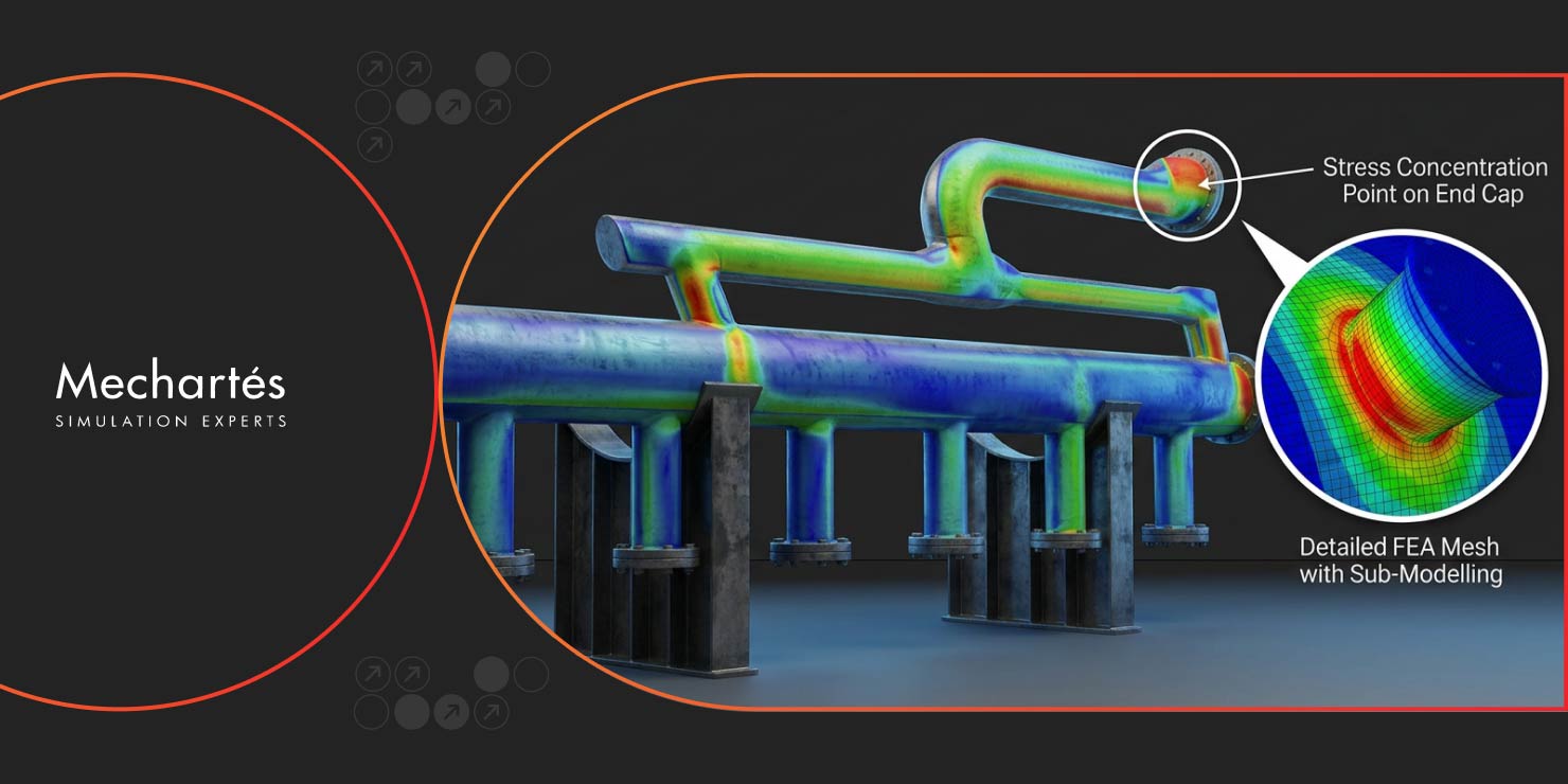
When we examined the existing design through FEA, several areas of concern emerged. High stress concentrations appeared at the cap-to-flange junction, around the extruded manway opening, and in specific regions of the curved head geometry.
These stress concentrations weren’t random. They appeared at locations where geometry changes create local stiffness discontinuities. At the cap-to-flange junction, the transition from the curved head to the cylindrical flange creates a geometric discontinuity that concentrates stress. The extruded manway represents a penetration through the pressure boundary, which inherently creates stress elevation around its perimeter.
Under extreme loading conditions, the analysis showed stresses exceeding allowable limits established by ASME pressure vessel codes. This didn’t mean the component would fail immediately, but it indicated an insufficient safety margin for reliable long-term operation.
The issue wasn’t that the original design was fundamentally flawed. It was that certain geometric details created localized stress levels that, while perhaps acceptable for static loading, didn’t provide adequate margin when considering the full spectrum of operating conditions, thermal effects, and cyclic loading the component would experience in service.
The analysis provided a detailed visualization of stress distribution throughout the component under each loading condition. This allowed us to identify not just where stresses were high, but why they were high and what geometric modifications would be most effective in reducing them.
The primary modification involved adding a reinforcement pad over the head in the high-stress region. This reinforcement wasn’t arbitrary thickening of the entire component, which would add unnecessary weight and material cost. Instead, it targeted the specific area where stress concentration occurred.
The reinforcement pad effectively redistributes the load over a larger area, reducing the peak stress at the critical location. The sizing and positioning of this pad were optimized through iterative FEA runs to achieve the necessary stress reduction while minimizing added weight.
Beyond the reinforcement pad, we adjusted local geometric details to improve stress distribution across critical regions. This included optimizing fillet radii at transitions, adjusting wall thickness gradients in specific zones, and refining the geometry around the manway opening.
These modifications represent targeted engineering rather than conservative overdesign. Each change addressed a specific stress concentration mechanism identified through the FEA results.
After implementing the design modifications, the component was re-analyzed under the full range of loading conditions to verify performance.
Stress levels in all critical regions were reduced to well within allowable limits established by ASME Section VIII Division 2. The design now provided adequate safety margin under operating pressure, design pressure, and hydrostatic test conditions.
Thermal stress analysis confirmed that temperature variations during operation wouldn’t create excessive combined stresses when superimposed with pressure loads. Lifting analysis verified that the component could be safely handled during installation and maintenance operations without risk of overstress or permanent deformation.
The modified design achieved full compliance with applicable ASME codes while maintaining practical fabricability and avoiding unnecessary weight or material cost.
This project illustrates several important points about design validation for critical pressure equipment.

FEA reveals stress distribution patterns that aren’t apparent from geometry or hand calculations. While experienced engineers can predict general areas of stress concentration, FEA quantifies the magnitude and extent of these concentrations with precision that supports confident design decisions.
High-stress areas consistently appear at geometric transitions: where curved surfaces meet flat surfaces, where different thicknesses join, where penetrations interrupt continuous surfaces. These are the locations that require the most attention during design and the most rigorous validation.
Understanding exactly where and why stress concentrations occur allows for targeted modifications that solve the problem without overbuilding the entire component. A well-placed reinforcement pad or optimized fillet radius can eliminate a stress concentration more efficiently than simply increasing wall thickness everywhere.
Identifying design weaknesses through FEA before fabrication allows modifications to be made when they’re least expensive. Discovering structural inadequacies during pressure testing, or worse, during operation, represents a fundamentally different cost and safety scenario.
At Mechartes, our approach to pressure vessel and component design validation combines ASME code requirements with detailed FEA to ensure critical equipment meets not just minimum compliance standards but performs reliably throughout its service life.
This slug catcher cap project demonstrates how simulation-driven design validation identifies potential issues, guides targeted improvements, and provides documented evidence of compliance before fabrication begins. The result is equipment that operators can trust to perform safely under all specified operating conditions.
For oil and gas facilities where pressure equipment integrity directly impacts safety and operational reliability, this level of design validation isn’t optional. It’s fundamental to responsible engineering practice.
Ready to discuss FEA-based design validation for your pressure equipment? Contact us to explore how detailed structural analysis can ensure your critical components meet performance requirements and code compliance.