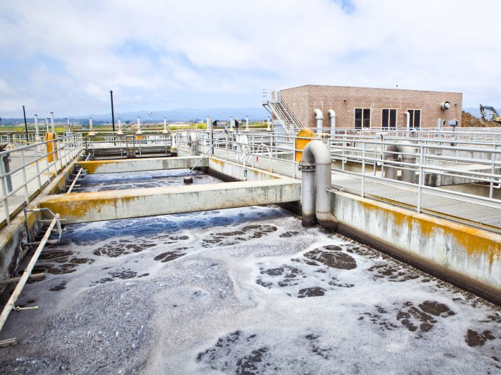
Primary Settling Tanks (PSTs) remove suspended particles from raw wastewater in Wastewater Treatment Plants (WWTPs). Since the PSTs represent the first stage of the treatment, the effectiveness of their operation affects the succeeding biological and sludge treatment units. The PST’s performance and efficiency also affect the production of biogas and electric energy in systems with anaerobic digestion and cogeneration.
Computational Fluid Dynamics (CFD) models are effective tools for designing and enhancing PST design and efficiency.
CFD Wastewater Treatment Plants

The Primary and Secondary Settling Tanks’ (SST) flow patterns have various density currents caused by the wastewater and suspended particles. As a result, the inlets’ and baffles’ designs are slightly different from those in regular tanks.
Recirculation zones, bottom currents, turbulence, density currents, and thermal density currents caused by changing the water inflow temperatures as well as surface heat exchange are further differences in a PST. These differences can significantly influence the effectiveness of the PST.
Hence, CFD is used to identify the optimal design of a PST to handle the varying conditions and different factors in the inflow water.
CFD models are extensively used to gain more knowledge of the various phenomena and their interactions in the sedimentation tank to predict tank performance accurately.
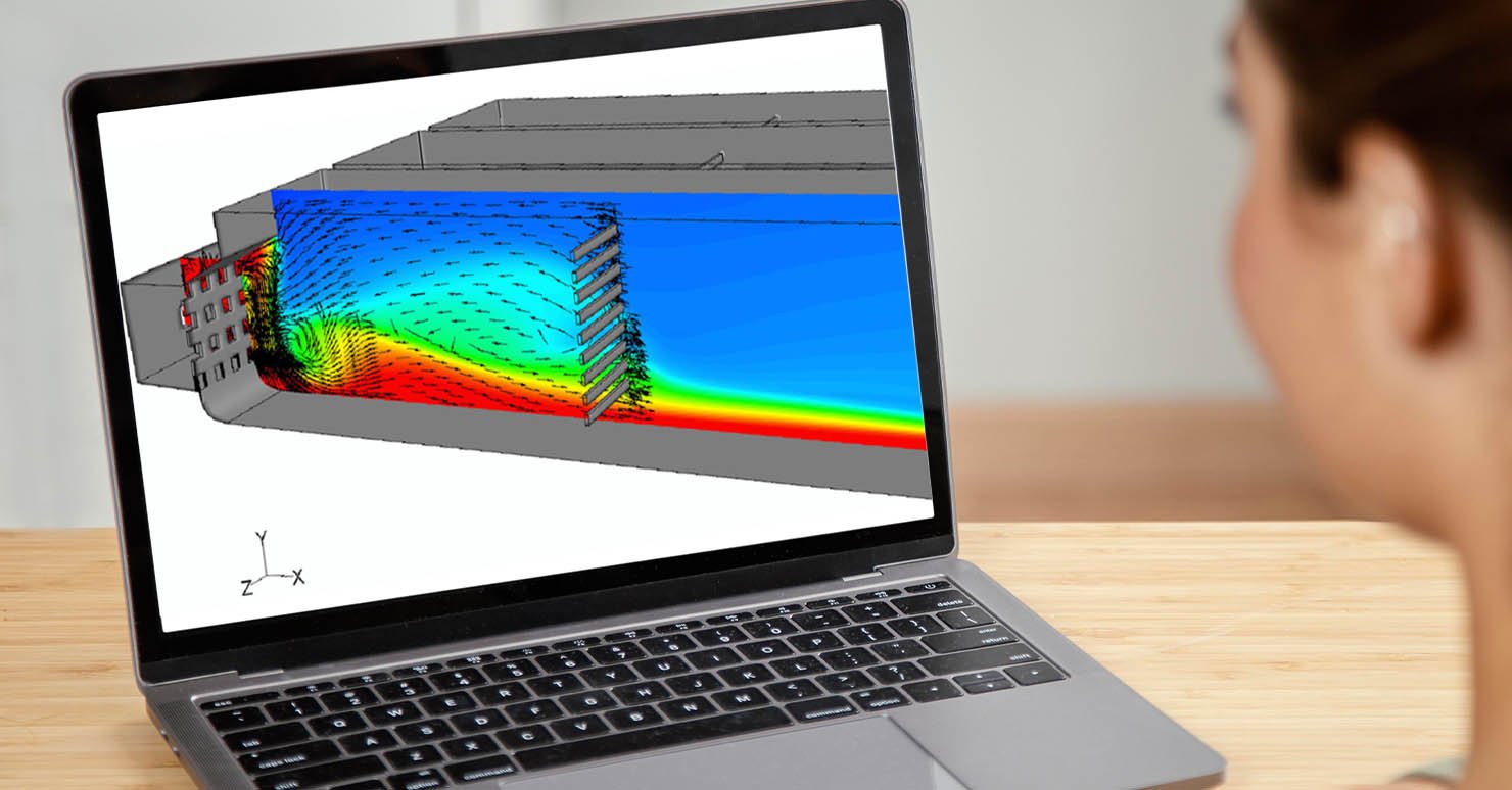
A 3D CFD model can completely resolve complicated non-symmetric geometry and phenomena, which may be utilized safely to simulate non-symmetric influent topologies, swirl effects caused by revolving scrapers, intake vanes, hydrodynamic circulation, and turbulence difficulties. Due to its advantages of being stable, user-friendly, and ease of understanding, commercial CFD solution codes like ANSYS FLUENT have been utilized extensively for 3D secondary settling tanks and PST modeling for optimizing the tank design and enhancing their performance.
CFD Application has been widely utilized to examine the flow pattern of rectangular PSTs and to improve their design. CFD models can help investigate the ideal placement and size of the baffles for PSTs. Field tests can support results from the CFD modeling to maximize positive outcomes.
CFD model to study the PSTs can be easily done by following general guidelines of good modeling practice
-
clearly defining the modeling task’s objective with all project participants
-
data collection; defining the model configuration (mesh generation) and simulation settings
-
running the simulations
-
post-processing, calibration, and validation.
CFD Applications in Wastewater Treatment Plant
The CFD model can simulate and evaluate the flow patterns and solid settling with the existing PST set-up to determine the underlying reason for the apparent performances. The CFD model can suggest a new configuration to enhance the PST performance.
Under the CFD model, PSTs design components can evaluate the influent column, the feed well or Center Well (CW), the peripheral effluent weir, the sludge hopper, the rotating sludge scraper, and the sludge pipe.
The CFD simulation begins with meshing, followed by adding the boundary conditions and then running the simulation.
Meshing
The CFD meshing and geometry can be designed to evaluate complex parameters, including sensitivity analysis with the right mesh. Where there are bigger velocity gradients and velocity is anticipated to have a greater influence on the sedimentation process, the mesh density with the finest grid can be applied.
A mesh-independency study helps reduce errors brought on by the grid’s coarseness and find the ideal balance between simulation accuracy, numerical stability, convergence, and computing time.
Boundary Conditions
The PSTs consist of operating characteristics and boundary conditions entered in the CFD application before simulations are run. Typically, there are five distinct boundary types
Some boundary conditions are:
-
The flow rate and cross-sectional area of the intake pipe
-
The flow rate and input velocity.
-
Outflow boundary for the sludge-withdrawal exit and effluent weir where there is no need to specify any constraints for this kind of border.
-
The walls are set up as “stationary walls.”
-
The free water surface is assigned as a symmetry plane where variations in the locations of the water surface are minimal.
Results and Interpretation
Once the simulation is run, the results are listed as a table or as 3D graphic images or animations that CFD experts can study and analyze the design conditions and performance and optimize to improve the performance of PSTs.
CFD Application for WTP with Mechartes
Mechartes can be a great resource to businesses and engineering designers when dealing with CFD applications for fluid flow analysis. Our expert CFD specialists are well versed in software applications with adequate training for mesh designing, applying boundary conditions, and result in interpretation.
With our expertise and industry knowledge, we can help enhance wastewater treatment plants with robust CFD Application capabilities and versatile validation services. Contact us today to get more information.


 Share
Share  facebook