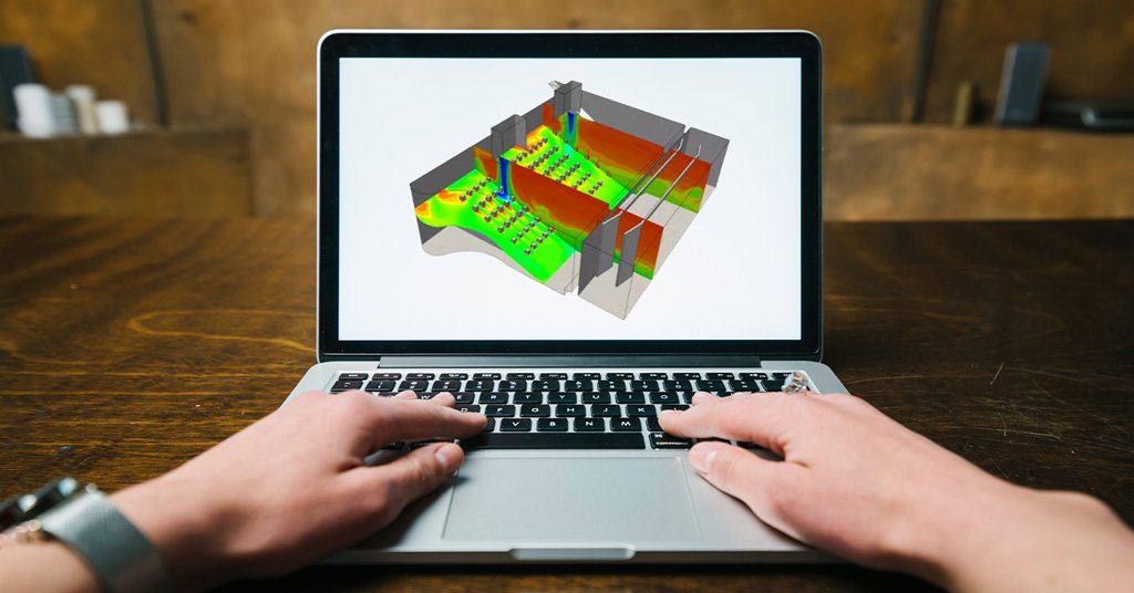
As we are advancing in science, the world around us is also changing noticeably. From merely fans and coolers to AC and HVAC, we have made good progress in creating a convenient lifestyle.If you are an HVAC designer or interested in CFD simulation for HVAC, this article will help you understand the different methods of using CFD simulation for HVAC system design.
What is Computational Fluid Dynamics?
Before exploring the different methods of using CFD simulation, let’s explore what CFD is. CFD stands for Computational Fluid Dynamics. It is a software-based analysis for fluid or thermal energy checks. It helps analyze the complex problems involving different phase interactions. The phase interaction can be between fluid-fluid, fluid-solid, or even fluid-gas.
CFD analysis is broadly used in the fields of Engineering like Hypersonics, Environmental Science, Aerodynamics, Hydrodynamics, Industrial Engineering, and Machinery Thermal Analysis. First, we must create the software’s mathematical model with consideration and boundary conditions. Then this mathematical model is solved using CFD software. An exciting thing about CFD software is that they run on algebraic equations.
What is HVAC?

HVAC stands for Heating, Ventilation, and Air Conditioning. In a way, it’s very similar to regular ACs, but there are differences. In an HVAC system, heat flows from higher temperature to lower or even from lower temperature to higher. The heat exchange occurs between the body and the environment and from the body to the body. Its primary focus is to provide good indoor air and a comfortable thermal environment. HVAC units are, however, massive in size and therefore are much preferred in big buildings currently.
Need for CFD Simulation for HVAC
The main reason to do the CFD simulation for HVAC is to save time and money in the design process. In addition, it is better than the conventional method for testing the mathematical model before beginning with the production part. All the desired quantities and parameters can be measured in this analysis. But the results are not a hundred percent accurate. The results may change or vary slightly because the actual condition is not ideal.
Phases of CFD analysis
Due to the complex nature of testing, the CFD simulation process is divided into the following three phases:
-
Pre-processing
-
Solving
-
Post-Processing
Pre-processing
In the first phase, the software creates a mathematical model. Then, it makes assumptions based on the actual condition this model will work in. Next, the problem statement is defined by giving the input values or boundary conditions. After setting the boundary conditions, the next thing is Mesh generation. It is similar to the meshing done in finite element testing. The selected region is divided into many bit-sized parts for easier and more accurate analysis.
Solving
The next step is Solving. After giving or setting the boundary conditions and creating a mesh on desired parts, it solves the mathematical model. There are various solvers available which have varying efficiency and capability of solving the algebraic questions, so all you need to do is enter the input values correctly in the pre-processing step for this step to function correctly.
Post-processing
It is the final step in CFD simulation for HVAC. The results are generated, displayed graphically and analyzed in a post-processing step. Finally, the conclusion is drawn based on obtained results. With this step, the simulation completes successfully.
Classification of CFD methods
As a vast discussion field, CFD has some essential methods for different requirements and usages. The five most prominent CFD analysis for HVAC are:
1. Finite Difference Method (FDM)
This method has a set of points that holds velocity, pressure, etc., that are the physical variables. CFD discretizes the Navier-Stokes Equation on these points, which are evenly distributed to make things simpler.
2. Finite Volume Method (FVM)
People often refer to FVM when they are trying to talk about CFD. However, FVM does more than CFD. It simulates the flow of fluid and thermal conditions as well. FVM divides the desired area of analysis into small control volumes. It is easy to understand due to the analogy between numerical concepts and physical meaning.
3. Finite Element Method (FEM)
FEM is the most widely used method to discretize a partial differential equation. It can even be an NSE. In addition, FEM is used to figure out problems based on fluid flow. In this method, the desired analysis area is divided into connected elements.
4. Lattice Boltzmann Method (LBM)
LBM is used for the approximation of macroscopic fluid phenomena as shock events (mesoscopic). It involves two steps:
Streaming – A particle exchange takes place between fictive particles and neighbouring cells.
Collision – Based on the particles streamed in the earlier step, computation of new mesoscopic quantities is done.
5. Smoothed Particle Hydrodynamics (SPH)
This method is typically based on Kernel functions, the Lagrangian particle discretization scheme. SPH also uses a velocity based technique in which we assume to put the particles of the desired analysis area in a river and let them flow.
More about CFD analysis on Mechartes
Get access to a lot more dynamics about CFD simulation of HVAC on our site – Mechartes. Get answers to all your questions about the CFD Analysis and Simulation field. Consult our experts and professionals who have worked in the field for more than 15 years.


 Share
Share  facebook