For the past 16 years, Mechartés has been operating on various complex and unique building and infrastructure projects in the Middle East and across the globe.
Our key focus lies in supporting clients to validate and optimize the HVAC design for high-value structures, such as data centres, malls, atria, airports, mosques, temples, and churches.
Here, we would like to share how Computational Fluid Dynamics (CFD), as a tool, helped a client optimize the HVAC design.
We will also evaluate our specific findings and purpose-driven insights from the thorough CFD analysis we performed for one of the Data Centers.
Let’s dive right in!
1. Introduction
A data center is a mission-critical infrastructure that hosts several computer servers. When these machines are operational, they produce an excessive amount of heat.
This necessitates developing suitable systems for real-time cooling.
Any procedural missteps and shortcomings can lead to a massive risk of failure due to the overheating of the equipment.
During the design process of a data center, Computational Fluid Dynamics (CFD) is extensively used to simulate and model the perfect HVAC system (Heating, Ventilation, and Air Conditioning) design. The goal is to understand the facility’s functionality as closely as possible and optimize the cooling system for various server rack load combinations.
CFD Analysis enables engineers to visualize and analyze the performance of the cooling system design to achieve the following:
-
Increase in the rack heat loads
-
Change in equipment layout
-
Failure scenarios
-
Day one analysis
-
Leakage analysis.
2. Objective
The main objective of the CFD analysis for the Project owners/contractors/design consultants is to:
-
Review whether proper air circulation is maintained or not.
-
Check whether the proper temperatures at the inlet of the server racks, i.e., within the ASHRAE recommended range, are maintained.
-
Ensure no hot spots on the server rack inlets.
-
Verify whether all IT and Network equipment are within the designed temperature range.
-
Inspect whether proper temperatures in the hot aisle are maintained or not without any hot spots in the data hall.
3. Scenarios
In this study, the analysis was carried out for the following scenarios:
-
Baseline model with all the units running ( N+2 or N+1).
-
Running of N units
-
Failure Mode – Transient simulation with failure of cooling units or power failure or switching between main power to generator power.
4. Modelling

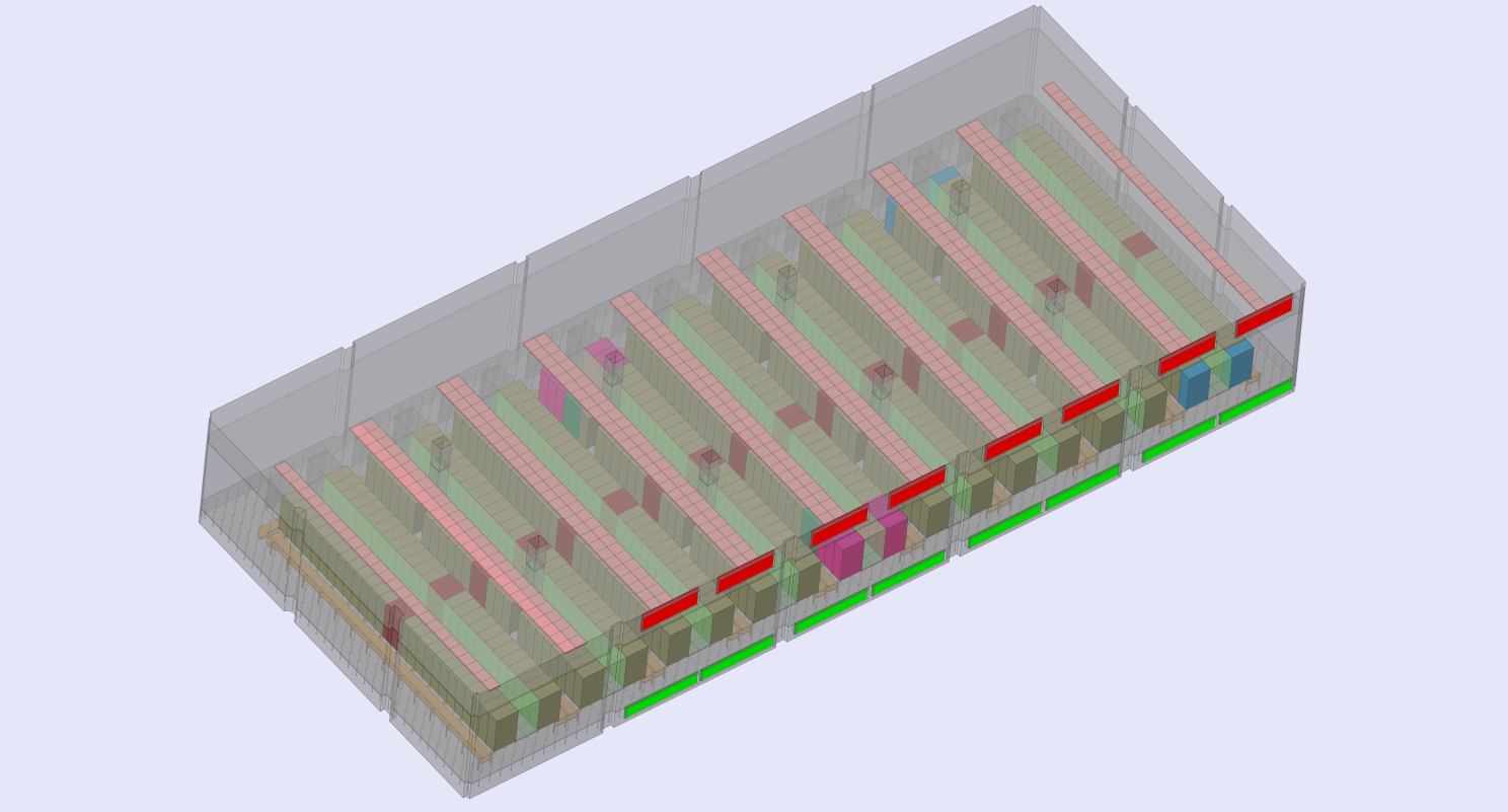
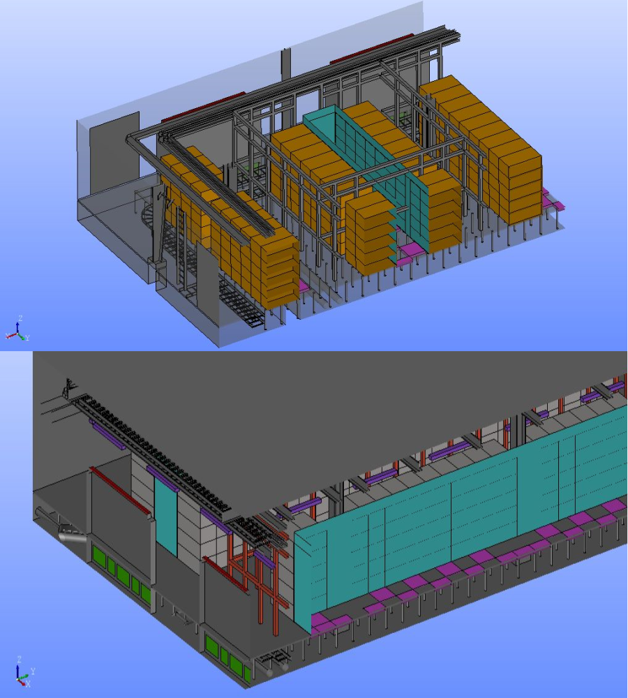
Per the inputs and design drawings received a detailed 3D model of the complete data hall was prepared in the CFD Software.
All the obstructions that would impact the airflow within the raised floor and the data hall were considered in the 3D Model.
Below the raised floors, the cable trays and the supports were modelled accurately, along with the discharge opening and the cold aisle perforated tiles.
Above the raised floors, all the obstructions, including the server racks and other impediments like cable trays, supports, trusses, electrical panels, perforated metal ceiling tiles, and lights below the false ceiling, were modelled in the CFD software.

5. Boundary Conditions
Optimized Cooling with CRAH Units
The Data Hall is equipped with bottom discharge and top suction CRAH units designed to regulate the temperature of the server racks efficiently. Each CRAH unit is connected via ductwork to motorized dampers, which manage discharge and suction (return air). These dampers are strategically positioned at the Data Hall’s perimeter, ensuring optimal airflow and cooling performance.
Efficient Airflow Management
Cold air is released through the discharge openings into the raised floor and is directed into the data hall’s cold aisle via perforated tiles. This cold aisle is contained, ensuring the cold air is channeled exclusively through the server racks, optimizing cooling efficiency and maintaining the desired temperature within the data hall.
Strategic Hot Air Extraction and Recirculation
Subsequently, the hot air emitted from the server racks is captured through perforated metallic ceiling grilles situated in the hot aisle’s false ceiling. This air is then redirected through the plenum space to the CRAH units’ suction (return air) openings, ensuring efficient heat removal and maintaining a controlled environment within the data hall.
Precision-Engineered Rack Airflow Design
The airflow configuration of the racks has been meticulously designed, allowing cold air to enter the server racks from the front at the cold aisle side. In contrast, hot air is expelled from the rear into the hot aisle, ensuring efficient circulation.
Modeling Supply Air Floor Tiles
The modeling of the supply air floor tiles was based on the relationship between pressure drop and volume flow rate, utilizing the characteristics provided for the tiles under the condition of fully open dampers.
Also, the leakage details for various elements were considered in the study. The heat loads of the server racks, lighting, People, and other equipment loads were considered in the model as per the input provided.
6. Conclusion and Recommendations
CFD Simulation to Assess Performance
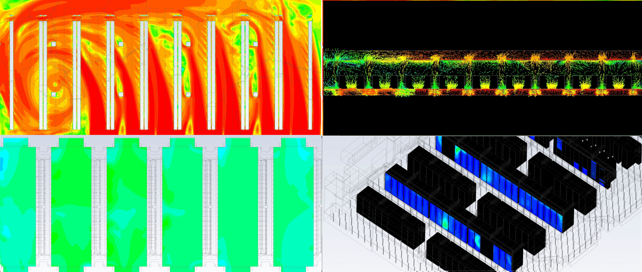
Upon completion of the 3D model, steady-state and transient CFD Simulation was performed for various scenarios to study the velocity, temperature, and pressure to evaluate the performance of the design cooling system.

Addressing Hot Spots through Airflow Optimization
The study revealed hot spots due to uneven airflow distribution from the floor tiles. To address this, multiple iterations involving the selective opening and closing of floor tiles were conducted to achieve uniform airflow throughout the tiles.
Optimized Floor Tile Configuration
The final design, featuring the optimized floor tile configuration, was proposed to ensure that the temperature at the server rack inlets remains within the specified design range.
Ensuring Temperature Control During Power Transition Scenarios
Further transient simulations were carried out with the finalized design for the failure scenario of switching main power to generator power. It was observed that there were no hotspots, and also the temperatures were within the ASHRAE recommended range.
Final Note
With Mechartés expertise in the CFD and numerical analysis and the recommendations mentioned, the client can come up with a conclusion on their design and way forward.
We at Mechartés focus on providing accurate simulation results with a professional engineering approach. Our biggest strength is our expertise and team of young, passionate engineers who work as a close-knit unit.
Feel free to share your comments and observations at srihari@mechartes.com. You can also leave a comment or write to us here.

