1. Objective
To examine the designed natural ventilation system effectiveness inside Transformer Room using Computational Fluid Dynamics (CFD) Analysis. The specific aim of the study involved to check the following parameters for the designed natural ventilation system and given heat load conditions from transformer surfaces of Inter Distribution Transformer Room:
-
To check if the proper air circulation is being maintained.
-
To check if the temperature of the transformer room is less than the designed temperature.

2. Modeling & Analysis

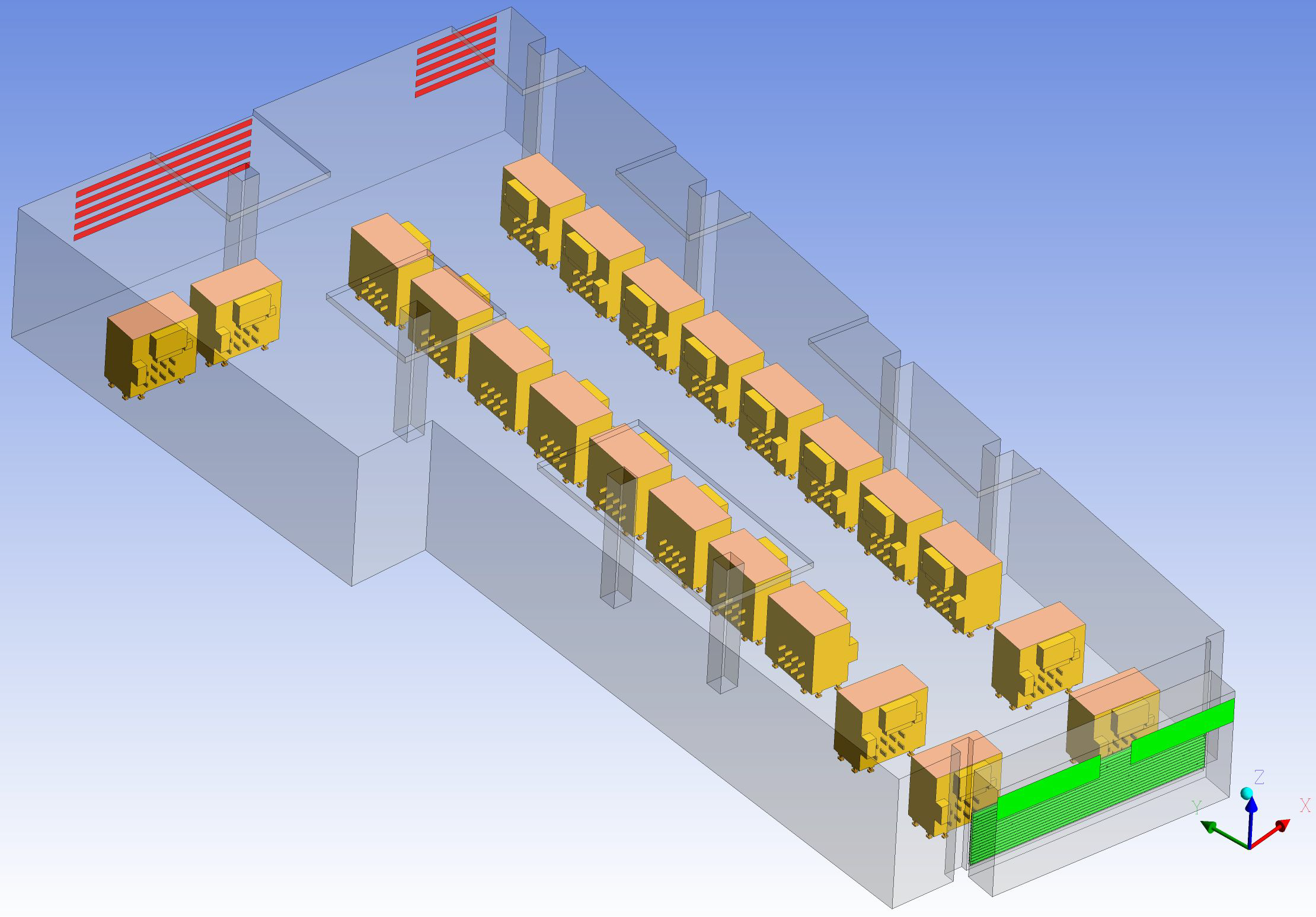
A geometrical model was made as per the site and the domain to be analyzed was divided into small volumes in CFD. The Navier-Stokes equation was solved for these volumes using numerical methods. The geometry was meshed with tetrahedral and hexahedral elements with varying size functions for small slots.
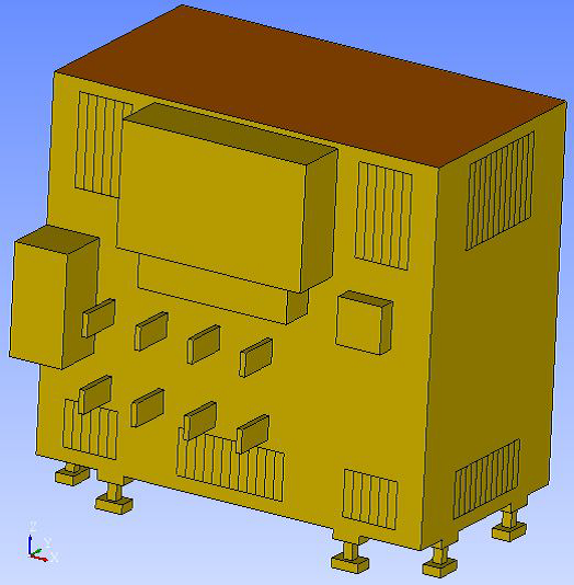
As per the transformer heat loss details received, the total heat loss’s from the Transformer (11/0.4 KV, 1500kVA, Tesar & Federal make) during the peak operating condition is 19.1 kW. So in order to reflect the peak operating condition at 48 0C ambient temperature, the total heat dissipation rate of 19.1 KW the heat load was distributed on the top & side surfaces of the transformer:
3. Output
-
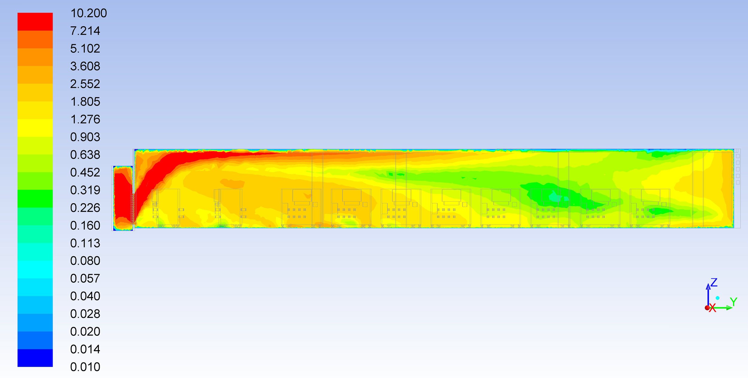
Velocity contour and profiles of hot air
-
Velocity vector profiles of hot air
-
Temperature profile at different levels/heights of hot air
-
Efficiency of the air circulation
-
Conclusion elucidating the outputs

4. Conclusion
It was observed that the average temperature obtained inside the transformer room area at various heights was less than the designed temperature.
From the velocity contour and flow distribution, it could be observed that the air circulation inside the room was properly distributed due to natural ventilation.


