1. Introduction

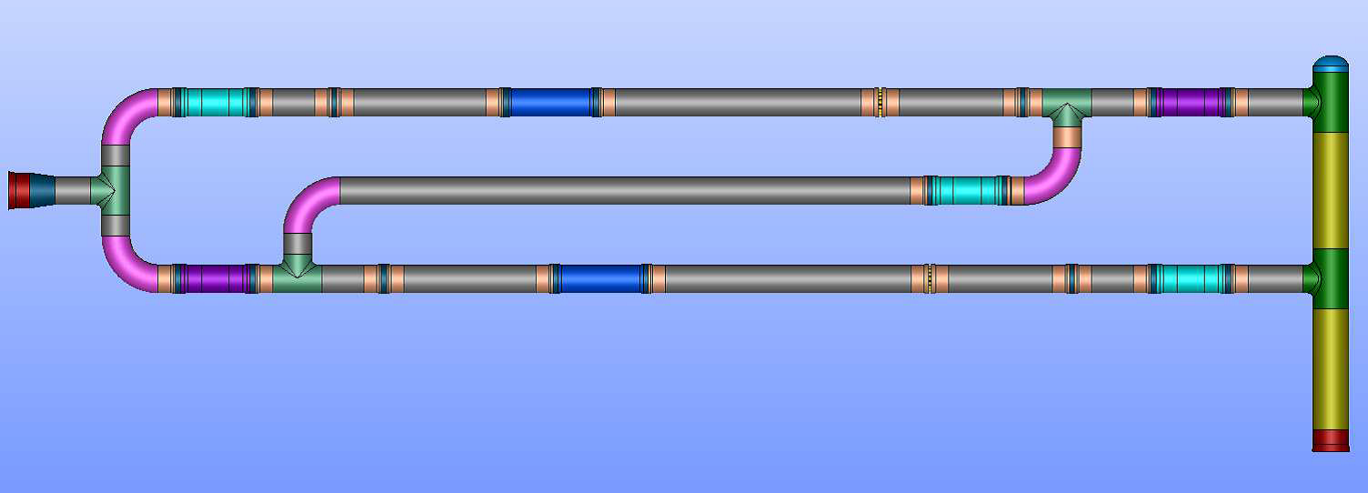
The metering stations are used mainly in the oil & gas industry for measuring the flow of gas along the pipelines and allow pipeline companies to monitor the natural gas in their pipelines.
These metering stations employ specialized meters such as ultrasonic flow meters to measure the natural gas as it flows through the pipeline, without impeding its movement. Typically, the ultrasonic flow metering stations will be a multi-path meter and the meter tubes will be equipped with a flow conditioner.
These ultrasonic flow meter tubes will be typically designed for a minimum 10D upstream length from the flow conditioner to the meter and 5D lengths downstream of the meter to precisely measure the flow.
2. Objective
The objective of the work is to conduct the CFD analysis for metering station network at various operating conditions to demonstrate the flow profiles within the metering station pipe network and mainly to check whether the fully developed flow profiles are achieved or not & is there any flow distortion near ultrasonic flow meters by studying the following parameters:
-
Axial flow profiles & Swirl angle profiles.
-
Transverse velocity magnitude profiles.
-
Horizontal transverse velocity & Vertical transverse velocity profiles.
3. Modeling and Analysis

The steady state CFD simulation was carried out by preparing the 3D model of the fluid zones of the natural gas metering pipe network by including the 0 components of Pipes, 90 Elbows, Tee sections, Grayloc hubs, Grayloc seal rings, Profiler plates (flow conditioners), Ball valves & Ultra sonic flow meters. The fluid domain to be analyzed is divided into small elements using a meshing software and compressible flow equations.
4. Conclusion

From the CFD results it was observed that the flow profiles in front of ultrasonic flow meters found to be fully developed and there was no major flow distortion as the swirl angle & various velocity profiles obtained were under the anticipated limits which can be observed in the following images

